How to Use KY-040: Examples, Pinouts, and Specs
Introduction
The KY-040 is a rotary encoder module that allows for precise control of position and rotation. Unlike a potentiometer, which provides an absolute position, the KY-040 outputs incremental signals, making it ideal for applications requiring relative position tracking. It features a built-in push button and provides two output signals (A and B) that can be used to determine the direction and amount of rotation.
Explore Projects Built with KY-040


Explore Projects Built with KY-040
Common Applications and Use Cases
- Volume control in audio devices
- Menu navigation in embedded systems
- Motor speed and position control
- Robotics and automation systems
- User input for microcontroller-based projects
Technical Specifications
The KY-040 rotary encoder module has the following key specifications:
| Parameter | Value |
|---|---|
| Operating Voltage | 3.3V to 5V |
| Output Type | Digital (Incremental) |
| Number of Pins | 5 |
| Push Button | Built-in |
| Rotational Steps | 20 steps per full rotation |
| Dimensions | 32mm x 19mm x 30mm |
Pin Configuration and Descriptions
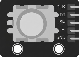
The KY-040 module has five pins, as described in the table below:
| Pin | Label | Description |
|---|---|---|
| 1 | GND | Ground connection |
| 2 | + | Power supply (3.3V to 5V) |
| 3 | SW | Push button output (active LOW) |
| 4 | DT | Data signal (Channel B) |
| 5 | CLK | Clock signal (Channel A) |
Usage Instructions
How to Use the KY-040 in a Circuit
- Connect the Power Supply: Connect the
+pin to a 3.3V or 5V power source and theGNDpin to ground. - Connect the Output Pins:
- Connect the
CLK(Channel A) andDT(Channel B) pins to digital input pins on your microcontroller. - Optionally, connect the
SWpin to a digital input pin if you want to use the push button.
- Connect the
- Read the Signals:
- Monitor the
CLKandDTsignals to determine the direction and amount of rotation. - The
SWpin can be used to detect button presses.
- Monitor the
Important Considerations and Best Practices
- Debouncing: The KY-040 outputs may produce noise or "bouncing" signals. Use software debouncing or external capacitors to ensure clean signal readings.
- Pull-up Resistors: If the
SWpin is not functioning as expected, ensure that a pull-up resistor is enabled in your microcontroller or added externally. - Power Supply: Ensure the module is powered within its operating voltage range (3.3V to 5V) to avoid damage.
Example: Using KY-040 with Arduino UNO
Below is an example Arduino sketch to read the KY-040 rotary encoder and detect rotation direction and button presses:
// Define KY-040 pins
#define CLK 2  // Clock pin (Channel A)
#define DT 3   // Data pin (Channel B)
#define SW 4   // Push button pin

int lastStateCLK;  // To store the previous state of the CLK pin
int currentStateCLK;  // To store the current state of the CLK pin
int counter = 0;  // Counter to track rotation
bool buttonPressed = false;  // Flag for button press

void setup() {
  pinMode(CLK, INPUT);
  pinMode(DT, INPUT);
  pinMode(SW, INPUT_PULLUP);  // Enable internal pull-up resistor for SW pin

  // Read the initial state of the CLK pin
  lastStateCLK = digitalRead(CLK);

  Serial.begin(9600);  // Initialize serial communication
}

void loop() {
  // Read the current state of the CLK pin
  currentStateCLK = digitalRead(CLK);

  // If the state of CLK has changed, a rotation has occurred
  if (currentStateCLK != lastStateCLK) {
    // Check the direction of rotation
    if (digitalRead(DT) != currentStateCLK) {
      counter++;  // Clockwise rotation
    } else {
      counter--;  // Counterclockwise rotation
    }

    // Print the counter value to the Serial Monitor
    Serial.print("Counter: ");
    Serial.println(counter);
  }

  // Update the last state of CLK
  lastStateCLK = currentStateCLK;

  // Check if the button is pressed
  if (digitalRead(SW) == LOW) {
    if (!buttonPressed) {
      Serial.println("Button Pressed!");
      buttonPressed = true;  // Set the flag to avoid multiple prints
    }
  } else {
    buttonPressed = false;  // Reset the flag when the button is released
  }
}
Troubleshooting and FAQs
Common Issues and Solutions
No Response from the Encoder:
- Ensure the power supply is connected correctly and within the specified voltage range.
- Verify that the
CLKandDTpins are connected to the correct microcontroller pins.
Incorrect Rotation Readings:
- Check for loose or faulty connections.
- Implement software debouncing to filter out noise from the encoder signals.
Push Button Not Working:
- Ensure the
SWpin is connected to a digital input pin with a pull-up resistor enabled. - Verify that the button is being pressed fully.
- Ensure the
Erratic or Unstable Readings:
- Add a small capacitor (e.g., 0.1µF) between the
CLKandGNDpins, and between theDTandGNDpins, to reduce noise.
- Add a small capacitor (e.g., 0.1µF) between the
FAQs
Q: Can the KY-040 be used with 3.3V microcontrollers like the ESP32?
A: Yes, the KY-040 is compatible with 3.3V systems. Ensure the power supply and signal levels match the microcontroller's requirements.
Q: How do I increase the resolution of the encoder?
A: The KY-040 has a fixed resolution of 20 steps per rotation. For higher resolution, consider using a different encoder with more steps.
Q: Can I use the KY-040 for absolute position tracking?
A: No, the KY-040 is an incremental encoder and does not provide absolute position information. It is best suited for relative position tracking.