How to Use esp 32 expanded board: Examples, Pinouts, and Specs
Introduction
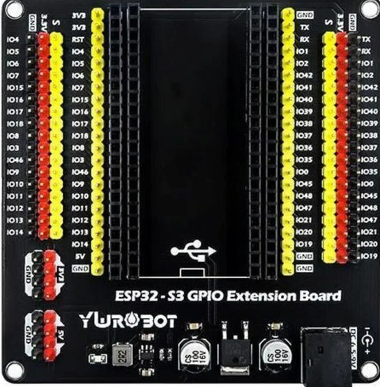
The ESP32-S3 Dev Board is a development board designed by Esp32, featuring the powerful ESP32-S3 chip. This board integrates Wi-Fi and Bluetooth connectivity, making it an ideal choice for IoT (Internet of Things) applications, smart devices, and rapid prototyping. With its expanded GPIO pins and additional interfaces, the ESP32-S3 Dev Board provides flexibility for a wide range of projects, from home automation to industrial monitoring.
Explore Projects Built with esp 32 expanded board
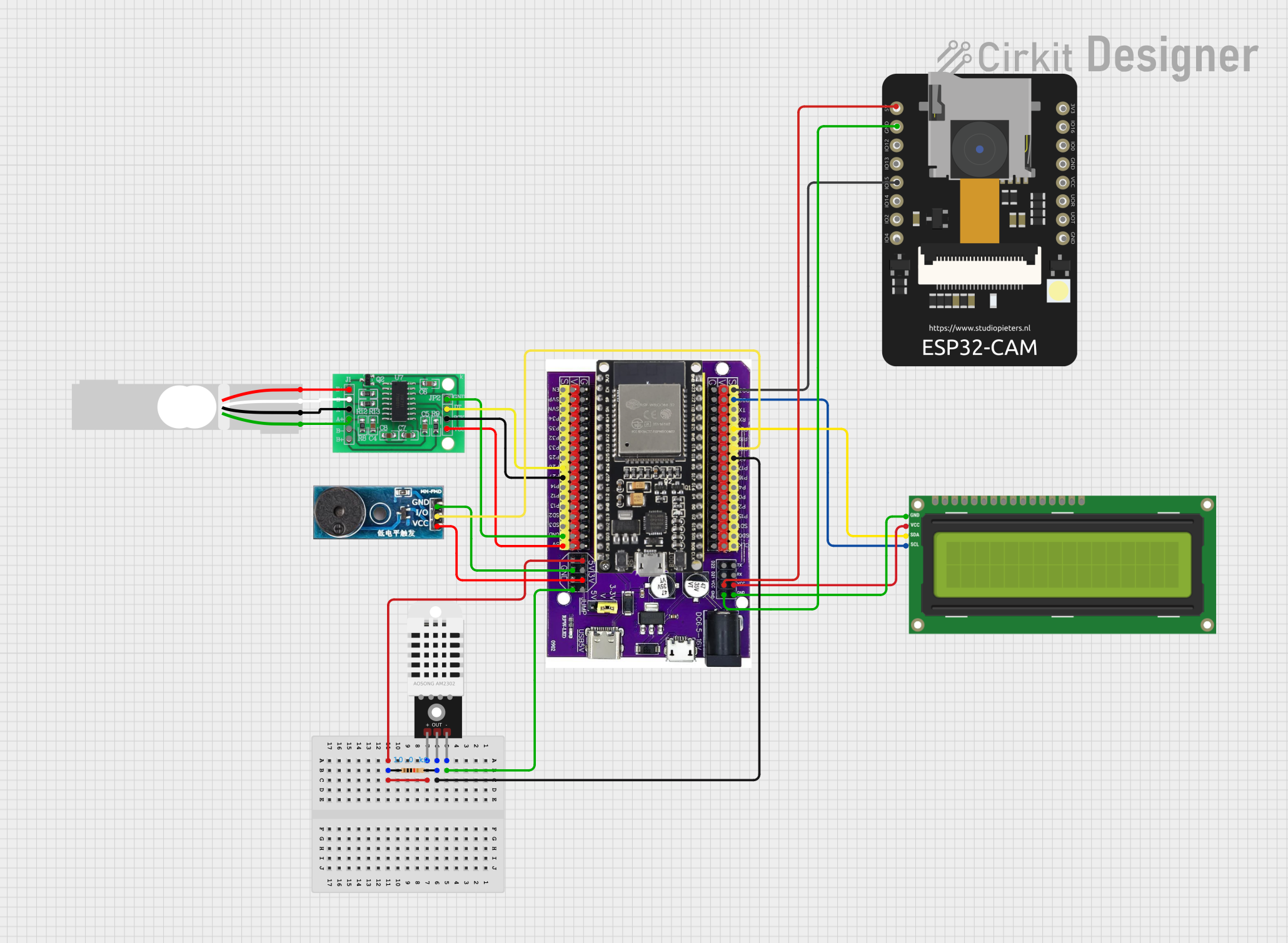
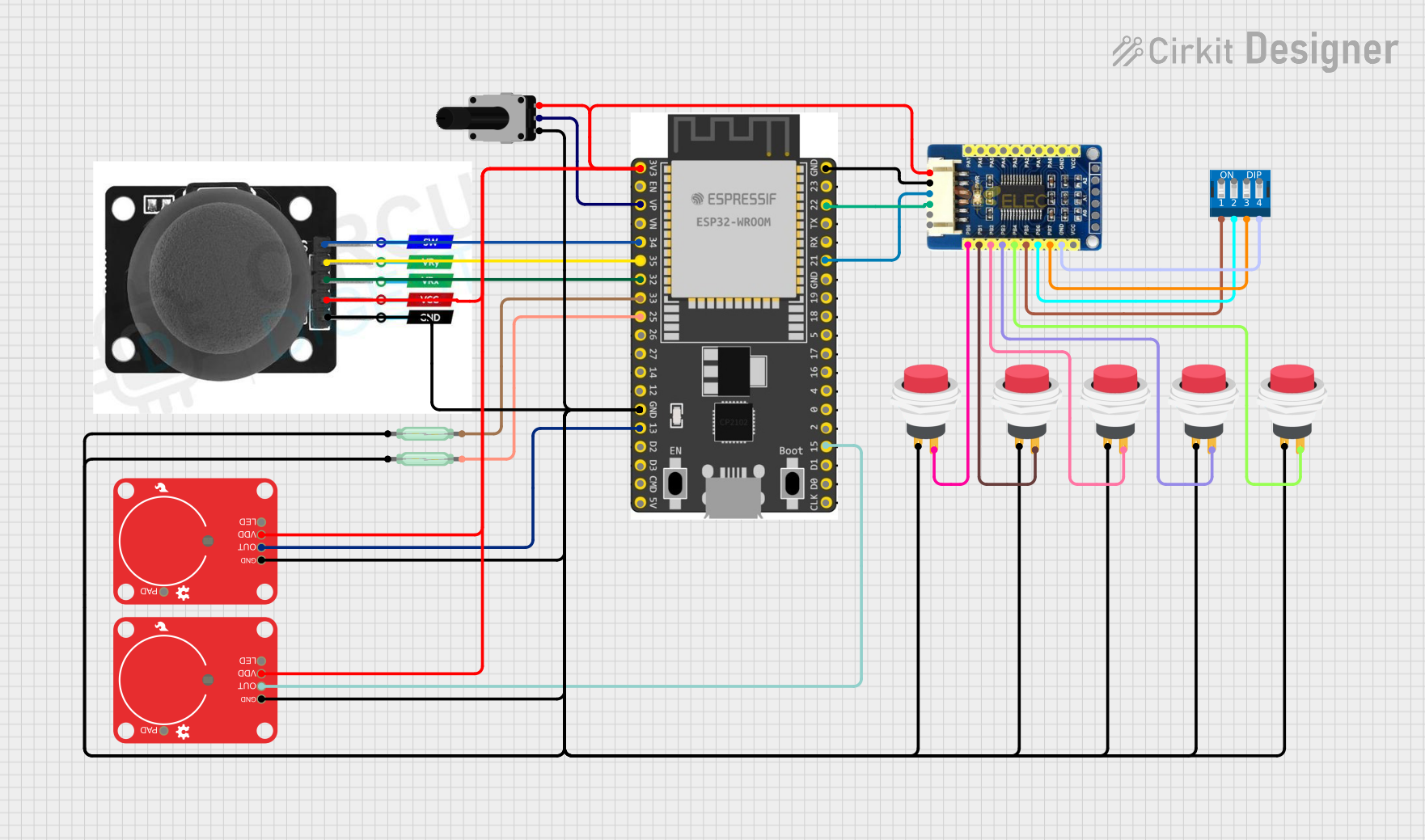


Explore Projects Built with esp 32 expanded board
Common Applications and Use Cases
- IoT devices and smart home systems
- Wireless sensor networks
- Prototyping for embedded systems
- Robotics and automation
- Wearable technology
- Data logging and remote monitoring
Technical Specifications
The ESP32-S3 Dev Board is packed with features that make it versatile and powerful for various applications. Below are the key technical specifications:
Key Technical Details
- Microcontroller: ESP32-S3 dual-core LX7 processor
- Clock Speed: Up to 240 MHz
- Wireless Connectivity:
- Wi-Fi: 802.11 b/g/n
- Bluetooth: BLE 5.0 + Bluetooth Classic
- Flash Memory: 4 MB (varies by model)
- SRAM: 512 KB
- GPIO Pins: 44 (expandable)
- Operating Voltage: 3.3V
- Input Voltage Range: 5V (via USB) or 3.3V (via pin)
- Interfaces: UART, SPI, I2C, I2S, PWM, ADC, DAC
- USB Interface: USB Type-C for programming and power
- Power Consumption: Ultra-low power consumption in deep sleep mode
- Dimensions: 54 mm x 25 mm (approx.)
Pin Configuration and Descriptions
The ESP32-S3 Dev Board features a variety of pins for interfacing with peripherals. Below is the pinout description:
| Pin Name | Type | Description |
|---|---|---|
| VIN | Power Input | Input voltage (5V) for powering the board via USB or external power supply. |
| GND | Ground | Ground connection. |
| 3V3 | Power Output | 3.3V output for powering external components. |
| GPIO0 | Digital I/O | General-purpose I/O pin, often used for boot mode selection. |
| GPIO1-44 | Digital I/O | General-purpose I/O pins for interfacing with sensors, actuators, and modules. |
| ADC1/ADC2 | Analog Input | Analog-to-digital converter pins for reading analog signals. |
| DAC1/DAC2 | Analog Output | Digital-to-analog converter pins for generating analog signals. |
| TX/RX | UART | Serial communication pins for UART interface. |
| SCL/SDA | I2C | I2C clock (SCL) and data (SDA) pins for I2C communication. |
| MOSI/MISO/SCK | SPI | SPI interface pins for high-speed communication with peripherals. |
| EN | Reset | Reset pin to restart the board. |
Usage Instructions
The ESP32-S3 Dev Board is easy to use and can be programmed using popular development environments like Arduino IDE or ESP-IDF. Below are the steps to get started and important considerations:
How to Use the Component in a Circuit
- Power the Board:
- Connect the board to your computer using a USB Type-C cable.
- Alternatively, supply 5V to the VIN pin or 3.3V to the 3V3 pin.
- Install Drivers:
- Ensure the appropriate USB-to-serial drivers are installed on your computer.
- Set Up the Development Environment:
- Install the Arduino IDE or ESP-IDF.
- Add the ESP32 board package to the Arduino IDE via the Board Manager.
- Connect Peripherals:
- Use the GPIO pins to connect sensors, actuators, or other modules.
- Ensure proper voltage levels and use pull-up or pull-down resistors if required.
- Upload Code:
- Write your program in the Arduino IDE or ESP-IDF.
- Select the correct board and port, then upload the code.
Important Considerations and Best Practices
- Voltage Levels: Ensure all connected peripherals operate at 3.3V logic levels to avoid damaging the board.
- Boot Mode: Use GPIO0 to enter bootloader mode if manual flashing is required.
- Power Supply: Use a stable power source to avoid unexpected resets or malfunctions.
- Deep Sleep Mode: Utilize the deep sleep mode for battery-powered applications to conserve energy.
Example Code for Arduino IDE
Below is an example code to blink an LED connected to GPIO2:
// Example: Blink an LED connected to GPIO2 on the ESP32-S3 Dev Board

#define LED_PIN 2  // Define the GPIO pin for the LED

void setup() {
  pinMode(LED_PIN, OUTPUT);  // Set the LED pin as an output
}

void loop() {
  digitalWrite(LED_PIN, HIGH);  // Turn the LED on
  delay(1000);                  // Wait for 1 second
  digitalWrite(LED_PIN, LOW);   // Turn the LED off
  delay(1000);                  // Wait for 1 second
}
Troubleshooting and FAQs
Common Issues and Solutions
- Board Not Detected by Computer:
- Ensure the USB cable is functional and supports data transfer.
- Install the correct USB-to-serial drivers for the ESP32-S3.
- Code Upload Fails:
- Check that the correct board and port are selected in the IDE.
- Press and hold the BOOT button while uploading the code.
- Wi-Fi Connection Issues:
- Verify the SSID and password in your code.
- Ensure the Wi-Fi network is within range and operational.
- Peripherals Not Responding:
- Double-check the wiring and connections.
- Ensure the peripherals are compatible with 3.3V logic levels.
FAQs
- Q: Can I power the board with a battery?
- A: Yes, you can use a 3.7V LiPo battery connected to the 3V3 pin or a 5V source to the VIN pin.
- Q: What is the maximum current output of the 3V3 pin?
- A: The 3V3 pin can supply up to 500 mA, depending on the input power source.
- Q: Can I use the ESP32-S3 Dev Board with MicroPython?
- A: Yes, the board supports MicroPython. You can flash the MicroPython firmware and use it for development.
This concludes the documentation for the ESP32-S3 Dev Board. For further assistance, refer to the official Esp32 documentation or community forums.