Cirkit Designer Logo
Cirkit Designer
Your all-in-one circuit design IDE
Home / 
Component Documentation

How to Use Adafruit 16x8 LED Matrix Backpack Orange: Examples, Pinouts, and Specs

Image of Adafruit 16x8 LED Matrix Backpack Orange
Cirkit Designer LogoDesign with Adafruit 16x8 LED Matrix Backpack Orange in Cirkit Designer

Introduction

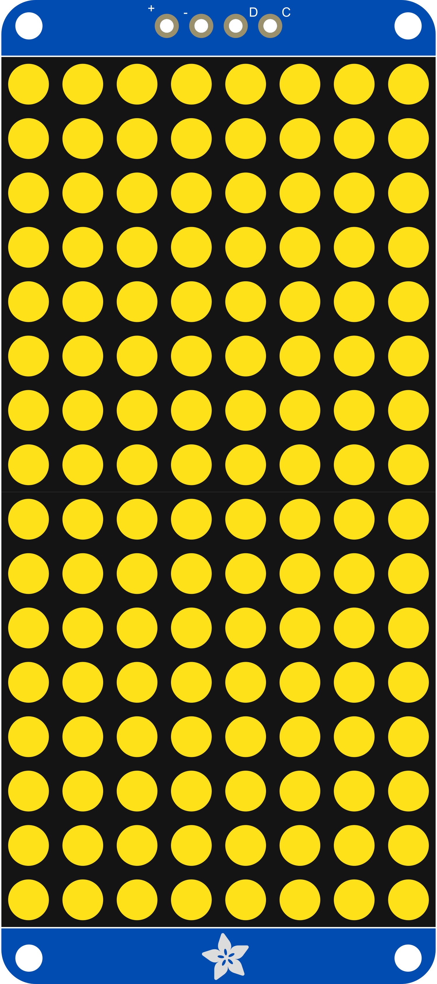
The Adafruit 16x8 LED Matrix Backpack is a versatile and visually striking electronic component designed to drive an 16x8 matrix of LEDs, providing a platform for creating dynamic displays and visual indicators. This orange variant of the LED matrix backpack offers a unique and vibrant color output, making it suitable for attention-grabbing signage, wearable electronics, and interactive art installations. It simplifies the process of controlling multiple LEDs by using the I2C interface, which minimizes the number of pins required from the controlling microcontroller, such as an Arduino UNO.

Explore Projects Built with Adafruit 16x8 LED Matrix Backpack Orange

Use Cirkit Designer to design, explore, and prototype these projects online. Some projects support real-time simulation. Click "Open Project" to start designing instantly!
ESP32-Controlled Dual 8x8 LED Matrix Display with NTP Time Synchronization
Image of time: A project utilizing Adafruit 16x8 LED Matrix Backpack Orange in a practical application
This circuit features an ESP32 microcontroller connected to two cascaded 8x8 LED matrix displays, powered by a 3.3V battery. The ESP32 drives the displays to show time and other information, with the code indicating functionality for connecting to WiFi, synchronizing time via NTP, and displaying data on the matrices using custom fonts. Additionally, there is a separate 3.3V battery powering a red LED, which appears to function as a simple indicator light.
Cirkit Designer LogoOpen Project in Cirkit Designer
Arduino UNO WiFi-Controlled LED Matrix Display
Image of SMD2121 Led screen - r4: A project utilizing Adafruit 16x8 LED Matrix Backpack Orange in a practical application
This circuit consists of an Arduino UNO R4 WiFi microcontroller connected to a 64x32 LED matrix. The Arduino controls the LED matrix by sending signals to various pins to display different colors and patterns, as defined in the embedded code.
Cirkit Designer LogoOpen Project in Cirkit Designer
Arduino-Controlled RGB LED Matrix Display
Image of SMD2121 Led screen: A project utilizing Adafruit 16x8 LED Matrix Backpack Orange in a practical application
This circuit connects an Arduino UNO R4 WiFi microcontroller to a 64x32 LED matrix display. The Arduino is configured to control the LED matrix, sending color data and control signals to display various colors across the matrix. The embedded code on the Arduino cycles through a range of colors, filling the entire LED matrix with each color in sequence.
Cirkit Designer LogoOpen Project in Cirkit Designer
Arduino UNO Controlled LED Matrix and LCD Interface with Joystick Interaction
Image of Digital Game Circuit: A project utilizing Adafruit 16x8 LED Matrix Backpack Orange in a practical application
This circuit features an Arduino UNO microcontroller interfaced with an 8x8 LED matrix, an LCD screen, and a KY-023 Dual Axis Joystick Module. The Arduino controls the LED matrix via digital pins D10-D12 and powers the matrix, LCD, and joystick module from its 5V output. The joystick's analog outputs are connected to the Arduino's analog inputs A0 and A1 for position sensing, while the LCD is controlled through digital pins D2-D6 and D13 for display purposes.
Cirkit Designer LogoOpen Project in Cirkit Designer

Explore Projects Built with Adafruit 16x8 LED Matrix Backpack Orange

Use Cirkit Designer to design, explore, and prototype these projects online. Some projects support real-time simulation. Click "Open Project" to start designing instantly!
Image of time: A project utilizing Adafruit 16x8 LED Matrix Backpack Orange in a practical application
ESP32-Controlled Dual 8x8 LED Matrix Display with NTP Time Synchronization
This circuit features an ESP32 microcontroller connected to two cascaded 8x8 LED matrix displays, powered by a 3.3V battery. The ESP32 drives the displays to show time and other information, with the code indicating functionality for connecting to WiFi, synchronizing time via NTP, and displaying data on the matrices using custom fonts. Additionally, there is a separate 3.3V battery powering a red LED, which appears to function as a simple indicator light.
Cirkit Designer LogoOpen Project in Cirkit Designer
Image of SMD2121 Led screen - r4: A project utilizing Adafruit 16x8 LED Matrix Backpack Orange in a practical application
Arduino UNO WiFi-Controlled LED Matrix Display
This circuit consists of an Arduino UNO R4 WiFi microcontroller connected to a 64x32 LED matrix. The Arduino controls the LED matrix by sending signals to various pins to display different colors and patterns, as defined in the embedded code.
Cirkit Designer LogoOpen Project in Cirkit Designer
Image of SMD2121 Led screen: A project utilizing Adafruit 16x8 LED Matrix Backpack Orange in a practical application
Arduino-Controlled RGB LED Matrix Display
This circuit connects an Arduino UNO R4 WiFi microcontroller to a 64x32 LED matrix display. The Arduino is configured to control the LED matrix, sending color data and control signals to display various colors across the matrix. The embedded code on the Arduino cycles through a range of colors, filling the entire LED matrix with each color in sequence.
Cirkit Designer LogoOpen Project in Cirkit Designer
Image of Digital Game Circuit: A project utilizing Adafruit 16x8 LED Matrix Backpack Orange in a practical application
Arduino UNO Controlled LED Matrix and LCD Interface with Joystick Interaction
This circuit features an Arduino UNO microcontroller interfaced with an 8x8 LED matrix, an LCD screen, and a KY-023 Dual Axis Joystick Module. The Arduino controls the LED matrix via digital pins D10-D12 and powers the matrix, LCD, and joystick module from its 5V output. The joystick's analog outputs are connected to the Arduino's analog inputs A0 and A1 for position sensing, while the LCD is controlled through digital pins D2-D6 and D13 for display purposes.
Cirkit Designer LogoOpen Project in Cirkit Designer

Technical Specifications

Key Technical Details

  • Operating Voltage: 4.5V to 5.5V
  • Max Current (per LED): 30mA
  • Max Current (for all LEDs): 1.2A
  • Communication Interface: I2C (TWI)
  • I2C Address: 0x70 (default, adjustable)
  • Dimensions: 1.2" x 1.9" x 0.1" (without headers)

Pin Configuration and Descriptions

Pin Number Name Description
1 GND Ground connection
2 VCC Power supply (4.5V to 5.5V)
3 SDA I2C Data line
4 SCL I2C Clock line
5 ADDR Address selection (connect to GND or VCC to change address)
6 RST Reset pin (optional use)

Usage Instructions

Connecting to a Circuit

  1. Power Supply: Connect the VCC pin to a 4.5V to 5.5V power supply and the GND pin to the ground of your system.
  2. I2C Communication: Connect the SDA and SCL pins to the corresponding I2C data and clock lines on your microcontroller.
  3. Address Selection: The ADDR pin can be left unconnected for the default address (0x70), or connected to GND or VCC to select an alternate address if multiple devices are on the same I2C bus.
  4. Reset (Optional): The RST pin can be connected to a digital pin on your microcontroller if you wish to control the reset function programmatically.

Programming with Arduino

To control the Adafruit 16x8 LED Matrix Backpack with an Arduino UNO, you will need to use the Adafruit LED Backpack library, which can be installed via the Arduino Library Manager.

Here is a simple example code to get started:

#include <Wire.h>
#include <Adafruit_GFX.h>
#include <Adafruit_LEDBackpack.h>

Adafruit_8x16matrix matrix = Adafruit_8x16matrix();

void setup() {
  matrix.begin(0x70); // Start the LED matrix with the I2C address
  matrix.setBrightness(10); // Set the brightness to a value between 0 and 15
}

void loop() {
  matrix.clear(); // Clear the matrix display
  matrix.setCursor(0, 0); // Set cursor at top-left corner
  matrix.print(F("Hello")); // Print a message on the matrix
  matrix.writeDisplay(); // Update the display with the new data
  delay(500); // Wait for half a second
}

Important Considerations and Best Practices

  • Power Requirements: Ensure that the power supply can handle the maximum current draw if all LEDs are lit.
  • I2C Addressing: When using multiple I2C devices, make sure each device has a unique address.
  • Brightness Control: Be mindful of the brightness level to avoid excessive current draw and to prolong the life of the LEDs.

Troubleshooting and FAQs

Common Issues

  • LEDs Not Lighting Up: Check the power supply connections and verify that the I2C lines are properly connected.
  • Garbled Display: Ensure that there are no conflicting I2C addresses and that the library and initialization code are correctly implemented.
  • Dim LEDs: Confirm that the brightness is set appropriately in the code and that the power supply is adequate.

Solutions and Tips for Troubleshooting

  • Check Connections: Double-check all wiring and solder joints for solid connections.
  • I2C Scanning: Use an I2C scanner sketch to verify that the Arduino can detect the LED matrix backpack.
  • Library Updates: Make sure you have the latest version of the Adafruit LED Backpack library.

FAQs

Q: Can I chain multiple LED matrix backpacks together? A: Yes, you can chain multiple units together by connecting their I2C lines in parallel and assigning unique addresses to each.

Q: How do I change the I2C address? A: The I2C address can be changed by connecting the ADDR pin to GND or VCC. Refer to the datasheet for the address mapping table.

Q: Can I use this LED matrix with a 3.3V system? A: The LED matrix is designed for 4.5V to 5.5V operation. Using it with a 3.3V system may result in dimmer LEDs or non-functioning display. Use a level shifter if necessary.

For further assistance, consult the Adafruit support forums or the detailed product guides available on the Adafruit website.