Cirkit Designer Logo
Cirkit Designer
Your all-in-one circuit design IDE
Home / 
Component Documentation

How to Use MG996R: Examples, Pinouts, and Specs

Image of MG996R
Cirkit Designer LogoDesign with MG996R in Cirkit Designer

Introduction

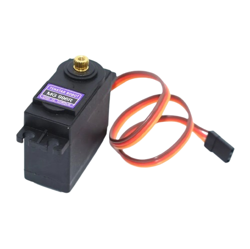
The MG996R is a high-torque digital servo motor that is widely used in the field of robotics and remote-controlled (RC) applications. It is an upgrade to the popular MG995 servo and is known for its improved performance and durability. The MG996R is suitable for various applications, including robotic arms, RC cars, helicopters, airplanes, and boats.

Explore Projects Built with MG996R

Use Cirkit Designer to design, explore, and prototype these projects online. Some projects support real-time simulation. Click "Open Project" to start designing instantly!
Arduino-Controlled Robotic Arm with Joystick and Push Button Interface
Image of ppp: A project utilizing MG996R in a practical application
This is a servo control system featuring an Arduino UNO that processes input from a dual-axis joystick and push switches to operate multiple MG996R servo motors. It is designed for precise multi-axis control, potentially for applications like robotics or remote-controlled mechanisms.
Cirkit Designer LogoOpen Project in Cirkit Designer
Arduino-Controlled Bluetooth Servo System with Adafruit PWM Driver
Image of glove new: A project utilizing MG996R in a practical application
This circuit is designed to wirelessly control multiple MG996R servos using an Arduino UNO and an Adafruit 16-Channel PWM Servo Driver. The HC-05 Bluetooth module enables remote command input, and a 3.7V battery provides power to the system.
Cirkit Designer LogoOpen Project in Cirkit Designer
ESP32-Based Automated Landing Gear System with Ultrasonic Sensor and LCD Display
Image of LANDING GEAR MECHANISMS: A project utilizing MG996R in a practical application
This circuit is an automated landing gear system for a model aircraft, utilizing an ESP32 microcontroller to control two servos based on input from an ultrasonic sensor and a toggle switch. The system displays distance measurements and gear status on a 16x2 LCD screen via an I2C interface.
Cirkit Designer LogoOpen Project in Cirkit Designer
Satellite-Based Timing and Navigation System with SDR and Atomic Clock Synchronization
Image of GPS 시스템 측정 구성도_Confirm: A project utilizing MG996R in a practical application
This circuit appears to be a complex system involving power supply management, GPS and timing synchronization, and data communication. It includes a SI-TEX G1 Satellite Compass for GPS data, an XHTF1021 Atomic Rubidium Clock for precise timing, and Ettus USRP B200 units for software-defined radio communication. Power is supplied through various SMPS units and distributed via terminal blocks and DC jacks. Data communication is facilitated by Beelink MINI S12 N95 computers, RS232 splitters, and a 1000BASE-T Media Converter for network connectivity. RF Directional Couplers are used to interface antennas with the USRP units, and the entire system is likely contained within cases for protection and organization.
Cirkit Designer LogoOpen Project in Cirkit Designer

Explore Projects Built with MG996R

Use Cirkit Designer to design, explore, and prototype these projects online. Some projects support real-time simulation. Click "Open Project" to start designing instantly!
Image of ppp: A project utilizing MG996R in a practical application
Arduino-Controlled Robotic Arm with Joystick and Push Button Interface
This is a servo control system featuring an Arduino UNO that processes input from a dual-axis joystick and push switches to operate multiple MG996R servo motors. It is designed for precise multi-axis control, potentially for applications like robotics or remote-controlled mechanisms.
Cirkit Designer LogoOpen Project in Cirkit Designer
Image of glove new: A project utilizing MG996R in a practical application
Arduino-Controlled Bluetooth Servo System with Adafruit PWM Driver
This circuit is designed to wirelessly control multiple MG996R servos using an Arduino UNO and an Adafruit 16-Channel PWM Servo Driver. The HC-05 Bluetooth module enables remote command input, and a 3.7V battery provides power to the system.
Cirkit Designer LogoOpen Project in Cirkit Designer
Image of LANDING GEAR MECHANISMS: A project utilizing MG996R in a practical application
ESP32-Based Automated Landing Gear System with Ultrasonic Sensor and LCD Display
This circuit is an automated landing gear system for a model aircraft, utilizing an ESP32 microcontroller to control two servos based on input from an ultrasonic sensor and a toggle switch. The system displays distance measurements and gear status on a 16x2 LCD screen via an I2C interface.
Cirkit Designer LogoOpen Project in Cirkit Designer
Image of GPS 시스템 측정 구성도_Confirm: A project utilizing MG996R in a practical application
Satellite-Based Timing and Navigation System with SDR and Atomic Clock Synchronization
This circuit appears to be a complex system involving power supply management, GPS and timing synchronization, and data communication. It includes a SI-TEX G1 Satellite Compass for GPS data, an XHTF1021 Atomic Rubidium Clock for precise timing, and Ettus USRP B200 units for software-defined radio communication. Power is supplied through various SMPS units and distributed via terminal blocks and DC jacks. Data communication is facilitated by Beelink MINI S12 N95 computers, RS232 splitters, and a 1000BASE-T Media Converter for network connectivity. RF Directional Couplers are used to interface antennas with the USRP units, and the entire system is likely contained within cases for protection and organization.
Cirkit Designer LogoOpen Project in Cirkit Designer

Technical Specifications

General Features

  • Type: Digital Servo
  • Gear Type: Metal Gears
  • Weight: 55g
  • Dimension: 40.7 x 19.7 x 42.9 mm

Performance

  • Operating Speed (4.8V): 0.17 sec/60°
  • Operating Speed (6.0V): 0.14 sec/60°
  • Stall Torque (4.8V): 9.4 kg-cm (130.5 oz-in)
  • Stall Torque (6.0V): 11 kg-cm (152.8 oz-in)

Electrical Specifications

  • Operating Voltage: 4.8V to 7.2V
  • Running Current: 500 mA
  • Stall Current: 2.5 A (at 6V)

Pin Configuration

Pin Number Description
1 Signal (PWM Input)
2 Voltage Supply (V+)
3 Ground (GND)

Usage Instructions

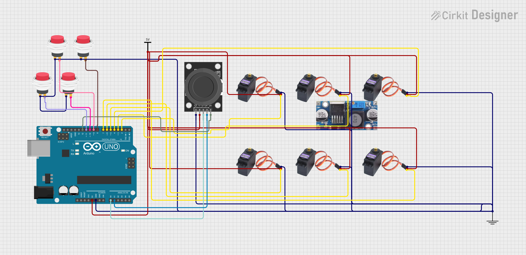
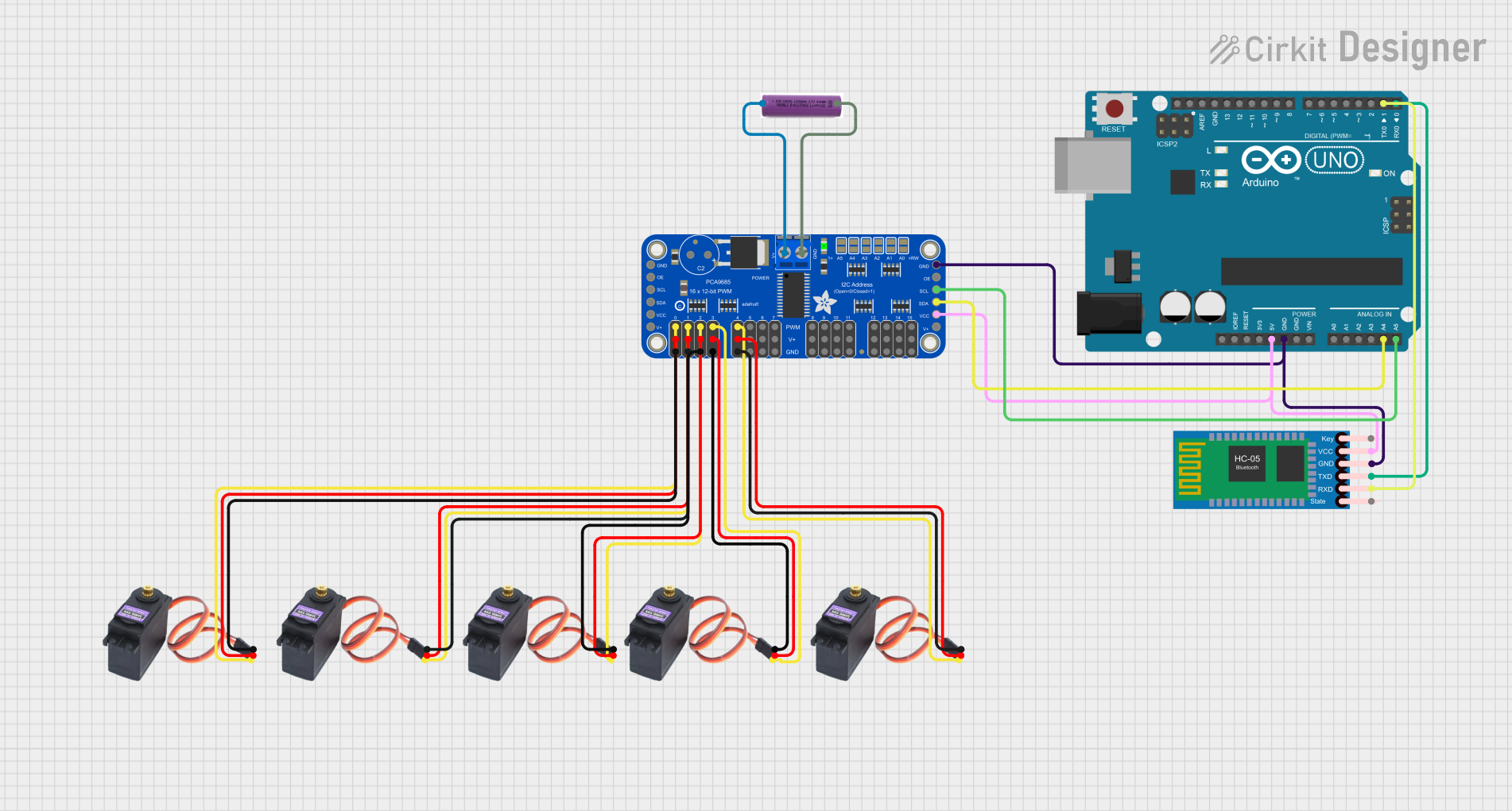
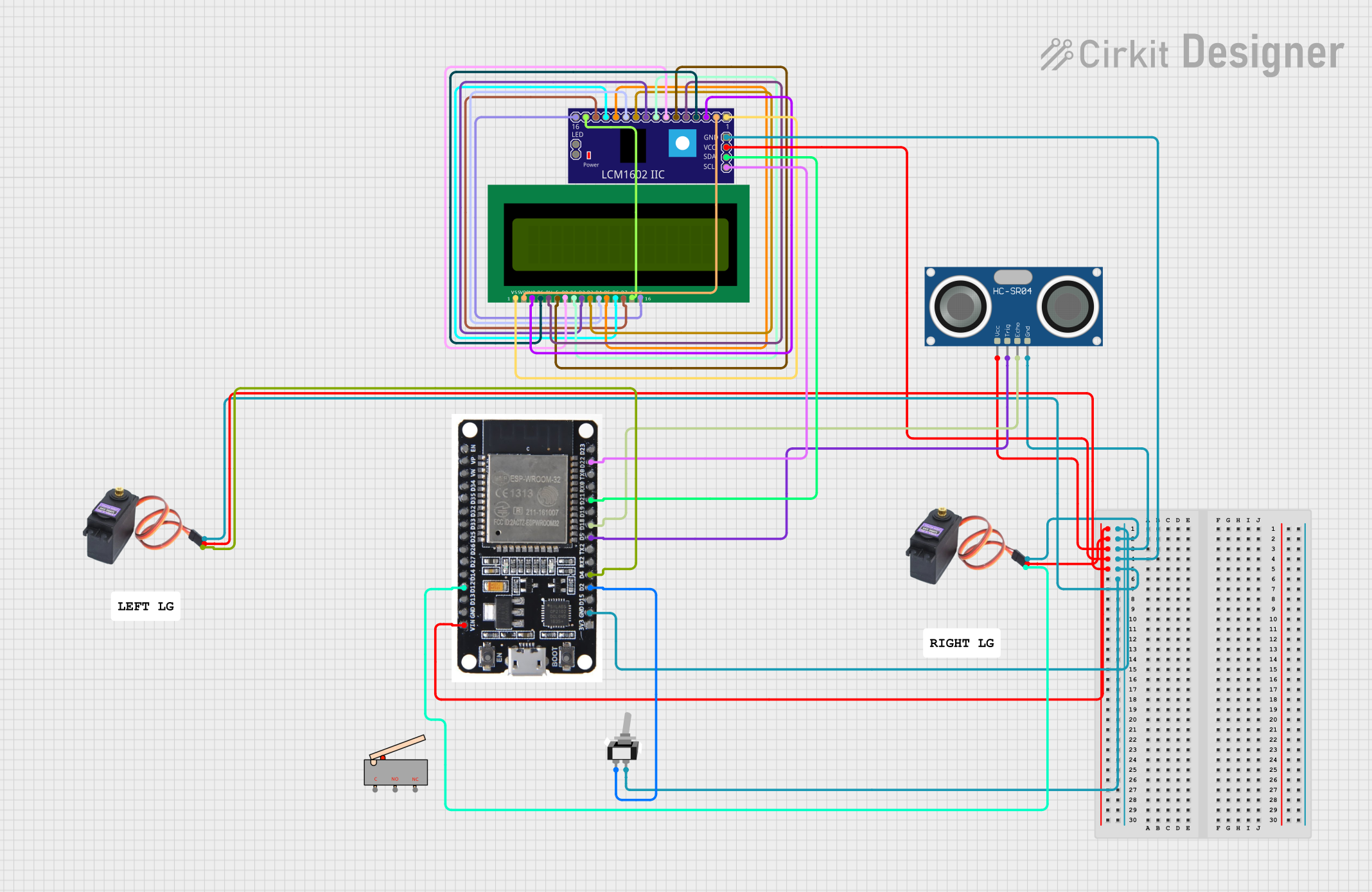
Connecting to a Circuit

  1. Power Supply: Connect the voltage supply pin to a power source that is within the operating voltage range of the MG996R. Ensure that the power supply can handle the stall current of the servo motor.
  2. Ground: Connect the ground pin to the common ground in your circuit.
  3. Signal: Connect the signal pin to a PWM-capable pin on your microcontroller, such as an Arduino UNO.

Best Practices

  • Always ensure that the power supply is disconnected before making any connections to prevent damage.
  • Avoid stalling the servo motor for extended periods, as this can lead to overheating and potential damage.
  • When mounting the servo, ensure that the load is within the servo's torque specifications to prevent strain and wear.

Example Code for Arduino UNO

#include <Servo.h>

Servo myservo;  // Create servo object to control the MG996R

void setup() {
  myservo.attach(9);  // Attaches the servo on pin 9 to the servo object
}

void loop() {
  myservo.write(0);   // Turn servo to 0 degrees
  delay(1000);        // Wait for 1 second
  myservo.write(90);  // Turn servo to 90 degrees (neutral position)
  delay(1000);        // Wait for 1 second
  myservo.write(180); // Turn servo to 180 degrees
  delay(1000);        // Wait for 1 second
}

Troubleshooting and FAQs

Common Issues

  • Servo not responding: Check connections, ensure the signal pin is connected to a PWM-capable pin, and verify that the power supply is within the specified range.
  • Servo jittering: This can be caused by an insufficient power supply or noise in the signal. Ensure a stable power source and check for any sources of interference.
  • Overheating: If the servo is overheating, it may be stalled or overloaded. Reduce the load or duty cycle to allow the servo to cool down.

FAQs

Q: Can I power the MG996R directly from an Arduino board? A: It is not recommended to power the MG996R directly from an Arduino board, as the servo may draw more current than the board can supply, especially under load. Use an external power source that meets the servo's requirements.

Q: What is the pulse width range for controlling the MG996R? A: The typical pulse width range for controlling the MG996R is 1000µs to 2000µs, with 1500µs being the neutral position (90 degrees).

Q: How do I calibrate the MG996R to my specific application? A: Calibration involves sending different pulse widths from your microcontroller and observing the servo's response. Adjust the pulse width until you achieve the desired position or range of motion.

Q: Can the MG996R be used for continuous rotation? A: The MG996R is not designed for continuous rotation out of the box. It is a standard servo with a limited range of motion (typically 180 degrees). However, it can be modified for continuous rotation by mechanically altering the internal feedback mechanism, but this is an advanced modification and not recommended for beginners.