How to Use Magnetic Reed Door Switch: Examples, Pinouts, and Specs
Introduction
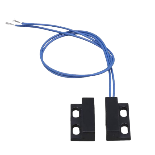
The Magnetic Reed Door Switch is a sensor designed to detect the opening and closing of doors or windows by utilizing a magnetic field. It consists of two main components: a reed switch and a magnet. When the door or window is closed, the magnet aligns with the reed switch, keeping the circuit closed. When the door or window opens, the magnet moves away, causing the circuit to open. This simple yet effective mechanism makes the Magnetic Reed Door Switch a popular choice for security systems, home automation, and industrial monitoring.
Explore Projects Built with Magnetic Reed Door Switch
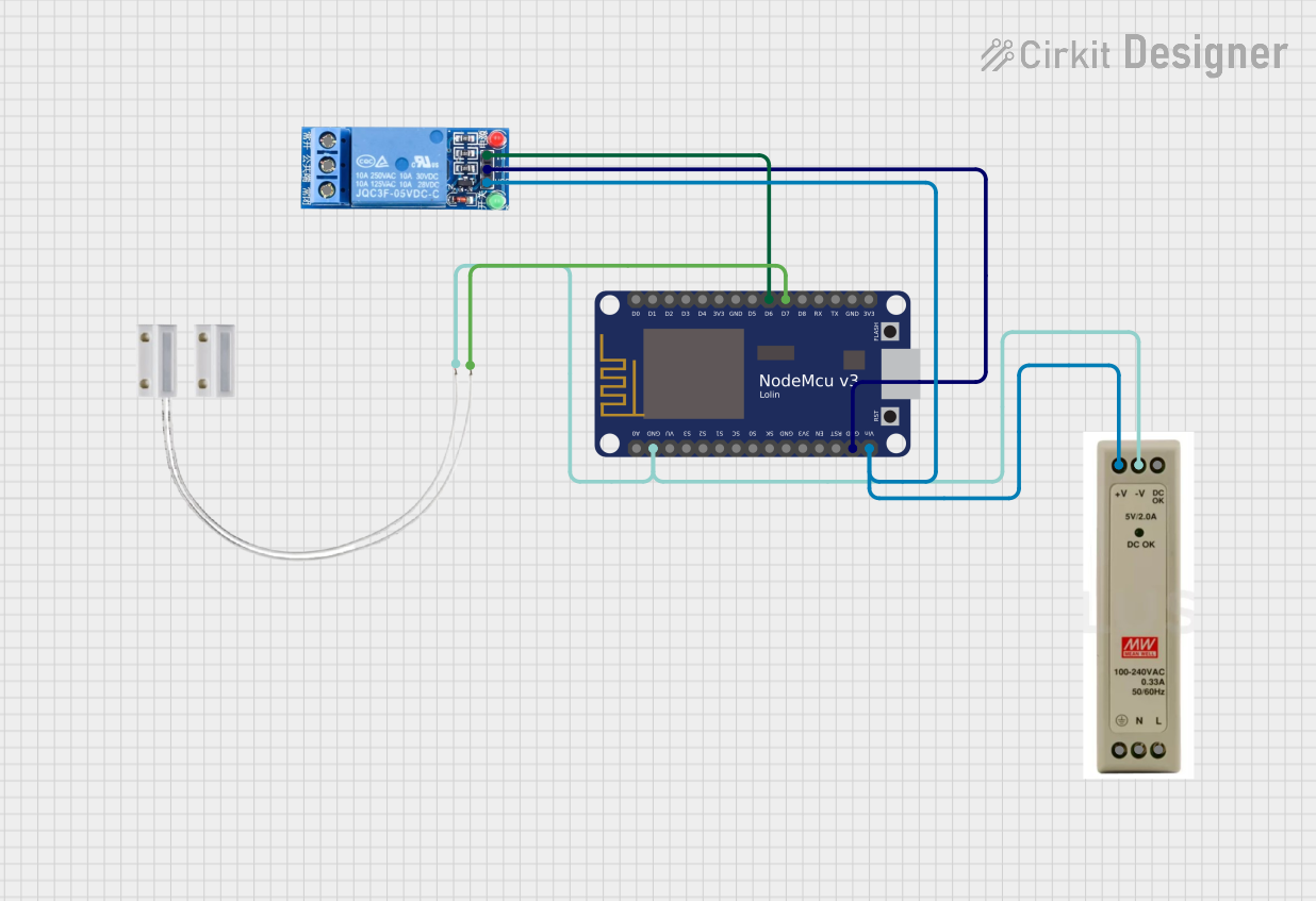
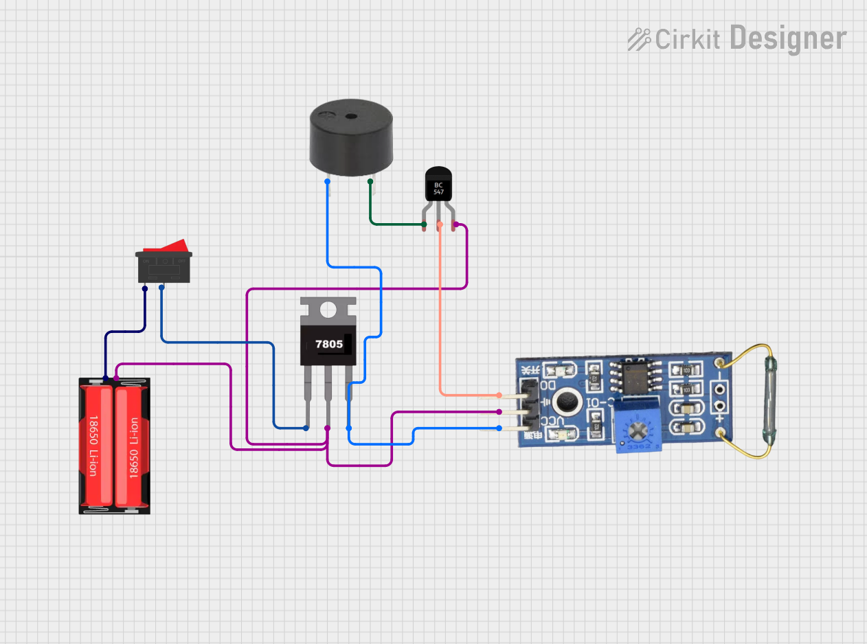
Explore Projects Built with Magnetic Reed Door Switch
Common Applications and Use Cases
- Home Security Systems: Detect unauthorized entry by monitoring door or window status.
- Smart Home Automation: Trigger actions such as turning on lights or sending notifications when a door is opened.
- Industrial Monitoring: Track the status of access points in warehouses or factories.
- Appliance Safety: Ensure doors on appliances like refrigerators or ovens are properly closed.
Technical Specifications
The Magnetic Reed Door Switch is a passive, normally open (NO) or normally closed (NC) device, depending on the configuration. Below are its key technical details:
Key Specifications
| Parameter | Value |
|---|---|
| Operating Voltage | 3V to 24V DC |
| Maximum Switching Current | 500 mA |
| Contact Resistance | ≤ 200 mΩ |
| Insulation Resistance | ≥ 10⁹ Ω |
| Operating Temperature | -40°C to +70°C |
| Housing Material | ABS Plastic |
| Magnet Type | Neodymium or Ferrite |
Pin Configuration and Descriptions
The Magnetic Reed Door Switch typically has two wires or terminals for connection. Below is the description:
| Pin/Terminal | Description |
|---|---|
| Wire 1 | Connects to the positive side of the circuit (input voltage). |
| Wire 2 | Connects to the load or ground, depending on the circuit design. |
Usage Instructions
How to Use the Magnetic Reed Door Switch in a Circuit
- Placement: Mount the reed switch on the stationary part of the door or window frame, and attach the magnet to the moving part (e.g., the door or window itself). Ensure the magnet aligns with the reed switch when the door is closed.
- Wiring:
- Connect one terminal of the reed switch to the positive voltage supply.
- Connect the other terminal to the input of your microcontroller, relay, or load.
- If using a microcontroller, add a pull-up resistor (e.g., 10kΩ) to ensure a stable signal.
- Testing: Close the door to verify that the circuit is completed (switch closed). Open the door to confirm the circuit opens (switch open).
Important Considerations and Best Practices
- Alignment: Ensure proper alignment between the reed switch and the magnet for reliable operation.
- Debouncing: When using the switch with a microcontroller, implement software or hardware debouncing to avoid false triggers caused by mechanical vibrations.
- Voltage and Current Ratings: Do not exceed the specified voltage and current ratings to prevent damage to the switch.
- Environmental Factors: Avoid exposing the switch to extreme temperatures, moisture, or strong magnetic fields, as these can affect performance.
Example: Connecting to an Arduino UNO
Below is an example of how to connect and use the Magnetic Reed Door Switch with an Arduino UNO:
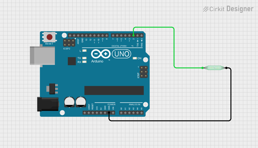
Circuit Diagram
- Connect one terminal of the reed switch to Arduino digital pin 2.
- Connect the other terminal to ground.
- Add a 10kΩ pull-up resistor between digital pin 2 and the 5V pin.
Code Example
// Magnetic Reed Door Switch Example with Arduino UNO
// This code reads the state of the reed switch and prints the status to the Serial Monitor.

const int reedSwitchPin = 2; // Pin connected to the reed switch
int reedState = 0;          // Variable to store the reed switch state

void setup() {
  pinMode(reedSwitchPin, INPUT_PULLUP); // Set pin as input with internal pull-up resistor
  Serial.begin(9600);                  // Initialize serial communication
}

void loop() {
  reedState = digitalRead(reedSwitchPin); // Read the state of the reed switch

  if (reedState == LOW) {
    // LOW means the reed switch is closed (door/window is closed)
    Serial.println("Door/Window is CLOSED");
  } else {
    // HIGH means the reed switch is open (door/window is open)
    Serial.println("Door/Window is OPEN");
  }

  delay(500); // Delay for stability and to avoid spamming the Serial Monitor
}
Troubleshooting and FAQs
Common Issues and Solutions
| Issue | Possible Cause | Solution |
|---|---|---|
| Switch does not detect door status | Misalignment between switch and magnet | Reposition the magnet and switch. |
| False triggers or unstable readings | Electrical noise or lack of debouncing | Add a pull-up resistor and debounce. |
| Switch is not working at all | Exceeded voltage/current ratings | Replace the damaged switch. |
| Magnet loses strength over time | Poor-quality magnet | Replace with a stronger magnet. |
FAQs
Can I use the Magnetic Reed Door Switch with AC circuits?
No, this switch is designed for low-voltage DC circuits only. Using it with AC may damage the switch.What is the maximum distance between the reed switch and the magnet?
The maximum distance depends on the strength of the magnet, but typically it is around 10-15 mm.Can I use multiple switches in a single circuit?
Yes, you can connect multiple switches in series or parallel, depending on your application.How do I protect the switch from environmental damage?
Use a weatherproof enclosure or seal the switch with epoxy to protect it from moisture and dust.