How to Use AUTOMATIC DC-DC 3.3V: Examples, Pinouts, and Specs
Introduction
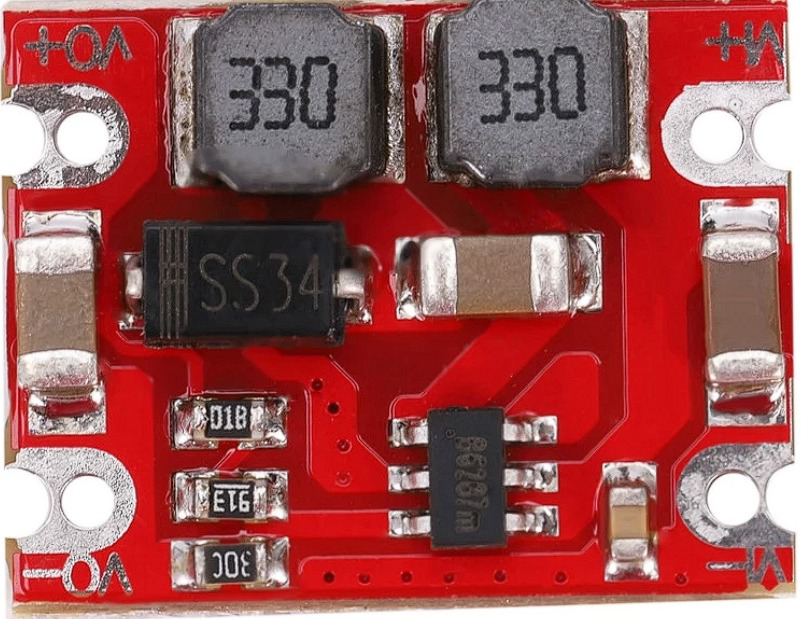
The AUTOMATIC DC-DC 3.3V is a compact and efficient voltage converter designed to automatically regulate input voltages to provide a stable 3.3V output. This component is widely used in power supply applications for electronic devices, particularly in scenarios where a consistent 3.3V is required for microcontrollers, sensors, and other low-power devices. Its automatic adjustment capability makes it ideal for battery-powered systems and projects requiring reliable voltage regulation.
Explore Projects Built with AUTOMATIC DC-DC 3.3V


Explore Projects Built with AUTOMATIC DC-DC 3.3V
Common Applications
- Powering microcontrollers (e.g., ESP8266, ESP32, etc.)
- Supplying stable voltage to sensors and modules
- Battery-powered devices and portable electronics
- Voltage regulation in embedded systems
Technical Specifications
The AUTOMATIC DC-DC 3.3V module is designed to handle a range of input voltages and provide a consistent 3.3V output. Below are the key technical details:
| Parameter | Specification |
|---|---|
| Input Voltage Range | 4.5V to 28V |
| Output Voltage | 3.3V (regulated) |
| Output Current | Up to 1A (depending on input voltage) |
| Efficiency | Up to 92% |
| Switching Frequency | 150 kHz |
| Operating Temperature | -40°C to +85°C |
| Dimensions | 22mm x 17mm x 4mm |
Pin Configuration and Descriptions
The module typically has three pins for easy integration into circuits:
| Pin Name | Description |
|---|---|
| VIN | Input voltage (4.5V to 28V) |
| GND | Ground (common ground for input and output) |
| VOUT | Regulated 3.3V output |
Usage Instructions
How to Use the Component in a Circuit
Connect the Input Voltage (VIN):
- Attach the positive terminal of your power source (e.g., battery or adapter) to the VIN pin. Ensure the input voltage is within the range of 4.5V to 28V.
Connect the Ground (GND):
- Connect the GND pin to the ground of your circuit. This serves as the common ground for both input and output.
Connect the Output Voltage (VOUT):
- Use the VOUT pin to power your 3.3V devices. Ensure the total current draw does not exceed the module's maximum output current (1A).
Verify Connections:
- Double-check all connections to avoid short circuits or incorrect wiring.
Power On:
- Turn on the power source. The module will automatically regulate the input voltage to provide a stable 3.3V output.
Important Considerations and Best Practices
- Input Voltage Range: Ensure the input voltage is within the specified range (4.5V to 28V). Exceeding this range may damage the module.
- Heat Dissipation: For high current loads, consider adding a heatsink or ensuring proper ventilation to prevent overheating.
- Capacitor Placement: Place decoupling capacitors (e.g., 10µF and 0.1µF) near the input and output pins to reduce noise and improve stability.
- Load Requirements: Avoid exceeding the maximum output current (1A) to prevent damage to the module or connected devices.
Example: Connecting to an Arduino UNO
The AUTOMATIC DC-DC 3.3V module can be used to power an Arduino UNO and other 3.3V peripherals. Below is an example of how to connect the module:
- Connect the VIN pin of the module to a 9V battery.
- Connect the GND pin of the module to the GND of the Arduino UNO.
- Connect the VOUT pin of the module to the 3.3V input of a sensor or module.
Sample Arduino Code for a 3.3V Sensor
// Example code to read data from a 3.3V sensor connected to an Arduino UNO
// Ensure the sensor is powered by the AUTOMATIC DC-DC 3.3V module

const int sensorPin = A0; // Analog pin connected to the sensor output

void setup() {
  Serial.begin(9600); // Initialize serial communication
  pinMode(sensorPin, INPUT); // Set the sensor pin as input
}

void loop() {
  int sensorValue = analogRead(sensorPin); // Read the sensor value
  float voltage = sensorValue * (3.3 / 1023.0); // Convert to voltage
  Serial.print("Sensor Voltage: ");
  Serial.print(voltage);
  Serial.println(" V");
  delay(1000); // Wait for 1 second before the next reading
}
Troubleshooting and FAQs
Common Issues and Solutions
No Output Voltage:
- Cause: Incorrect wiring or insufficient input voltage.
- Solution: Verify that the input voltage is within the specified range and check all connections.
Overheating:
- Cause: Excessive current draw or poor ventilation.
- Solution: Reduce the load current or add a heatsink to the module.
Output Voltage Fluctuations:
- Cause: Insufficient decoupling capacitors or unstable input voltage.
- Solution: Add capacitors (e.g., 10µF and 0.1µF) near the input and output pins.
Module Not Working:
- Cause: Damaged module due to overvoltage or reverse polarity.
- Solution: Replace the module and ensure proper polarity and voltage range.
FAQs
Q: Can this module power a 3.3V microcontroller directly?
A: Yes, the module is designed to provide a stable 3.3V output suitable for microcontrollers like ESP8266 or ESP32.
Q: What happens if the input voltage drops below 4.5V?
A: The module may fail to regulate the output voltage, leading to unstable or insufficient output.
Q: Can I use this module with a Li-ion battery?
A: Yes, as long as the battery voltage is within the input range (4.5V to 28V).
Q: Is the module protected against reverse polarity?
A: Most modules do not include reverse polarity protection. Always double-check your connections to avoid damage.