How to Use 16 channel analog multiplexer bob: Examples, Pinouts, and Specs
Introduction
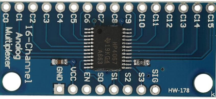
The CD74HC4067 is a high-performance CMOS (Complementary Metal-Oxide Semiconductor) analog multiplexer/demultiplexer that allows the connection of 16 different analog inputs or outputs to a common analog bus. This component is manufactured by Texas Instruments and is widely used in applications that require multiple input signals to be routed to a single processing or output device, such as data acquisition systems, signal routing applications, and in scenarios where board space is at a premium.
Explore Projects Built with 16 channel analog multiplexer bob


Explore Projects Built with 16 channel analog multiplexer bob
Common Applications and Use Cases
- Analog signal multiplexing in data acquisition systems
- Channel selection in measurement equipment
- Audio signal routing
- Use in microcontroller-based projects, such as with Arduino platforms
- Prototyping and hobbyist electronics for sensor interfacing
Technical Specifications
Key Technical Details
- Operating Voltage Range: 2V to 6V
- On-State Resistance: 70 Ohms typical (@ Vcc = 4.5V)
- Off-State Leakage Current: ±0.5µA max (@ Vcc = 6V)
- Channel On/Off Time: 13ns typical
- Operating Temperature Range: -55°C to 125°C
Pin Configuration and Descriptions
| Pin Number | Name | Description |
|---|---|---|
| 1-16 | C0-C15 | Channel Inputs/Outputs |
| 17 | EN | Active Low Enable Input |
| 18-21 | S0-S3 | Binary Control Inputs |
| 22 | Vee | Ground Reference for Analog Signals |
| 23 | Z | Common Output/Input |
| 24 | Vcc | Positive Supply Voltage |
| 25 | GND | Ground (0V) |
| 26-29 | S4-S7 | No Connect (NC) in this device |
| 30 | E | Active High Enable Input |
| 31 | Vz | No Connect (NC) in this device |
| 32 | COM | Common Input/Output for Demultiplexer |
Usage Instructions
How to Use the Component in a Circuit
- Power Supply: Connect Vcc to a positive supply voltage (2V to 6V) and GND to the ground.
- Enable Pin: To enable the device, connect EN to ground (active low). The E pin is not used in this device and should be left unconnected.
- Channel Selection: Apply a binary code to the S0-S3 pins to select the desired channel (C0-C15).
- Analog Signal: Connect the analog signal(s) to the desired channel input(s) and the common output/input (Z) to the next stage in your circuit.
Important Considerations and Best Practices
- Ensure that the power supply voltage is within the specified range to avoid damaging the device.
- Avoid floating control inputs by connecting unused select pins to either Vcc or GND.
- Minimize noise by keeping analog signal paths as short as possible.
- Use bypass capacitors close to the Vcc and GND pins to filter out noise.
Troubleshooting and FAQs
Common Issues Users Might Face
- No Output Signal: Check if the EN pin is correctly connected to GND and that the correct channel is selected with the S0-S3 pins.
- Signal Distortion: Ensure that the operating voltage is stable and within the specified range. Also, check for proper grounding and use of bypass capacitors.
Solutions and Tips for Troubleshooting
- Verify that all connections are secure and correct.
- Use an oscilloscope to check for proper signal routing through the multiplexer.
- If experiencing unexpected behavior, double-check the binary code applied to the S0-S3 pins.
FAQs
Q: Can I use the CD74HC4067 with a microcontroller like an Arduino? A: Yes, the CD74HC4067 can be easily interfaced with an Arduino or similar microcontroller.
Q: What is the purpose of the Vee pin? A: The Vee pin is the ground reference for the analog signals. It should be connected to the system ground.
Q: Can I use this device for digital signals as well? A: Yes, the CD74HC4067 can be used to route digital signals, provided they are within the voltage range of the device.
Example Code for Arduino UNO
// Example code to control the CD74HC4067 using an Arduino UNO

const int controlPins[] = {2, 3, 4, 5}; // S0-S3 connected to Arduino digital pins 2-5
const int enablePin = 6; // EN connected to Arduino digital pin 6
const int sigPin = A0; // Z connected to Arduino analog pin A0

void setup() {
  // Set control pins as outputs
  for (int i = 0; i < 4; i++) {
    pinMode(controlPins[i], OUTPUT);
  }
  pinMode(enablePin, OUTPUT);
  digitalWrite(enablePin, LOW); // Enable the multiplexer
}

void loop() {
  for (int channel = 0; channel < 16; channel++) {
    setMultiplexerChannel(channel);
    int sensorValue = analogRead(sigPin); // Read the signal from the selected channel
    // Process the sensor value or send it to the serial monitor
    // ...
  }
}

void setMultiplexerChannel(int channel) {
  // Set the control pins to the binary equivalent of the channel number
  for (int i = 0; i < 4; i++) {
    digitalWrite(controlPins[i], (channel >> i) & 1);
  }
}
This example demonstrates how to cycle through all 16 channels of the CD74HC4067, reading an analog signal from each channel. The setMultiplexerChannel function sets the appropriate control pins to select the desired channel. Remember to adjust the pin numbers to match your specific setup.