
How to Use ST7789V_WAVESHARE_LCD_320x240: Examples, Pinouts, and Specs
 Design with ST7789V_WAVESHARE_LCD_320x240 in Cirkit Designer
Introduction
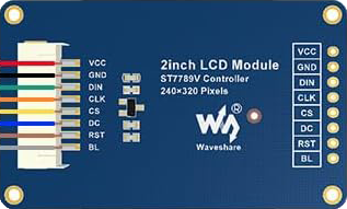
The ST7789V_WAVESHARE_LCD_320x240 is a 320x240 pixel color LCD display module manufactured by Waveshare. It is based on the ST7789V driver IC, which is widely used in embedded systems for rendering high-quality graphics and text. This display module is compact, energy-efficient, and supports multiple communication interfaces, making it ideal for a variety of applications.
Explore Projects Built with ST7789V_WAVESHARE_LCD_320x240
 Open Project in Cirkit Designer
 Open Project in Cirkit Designer
 Open Project in Cirkit Designer
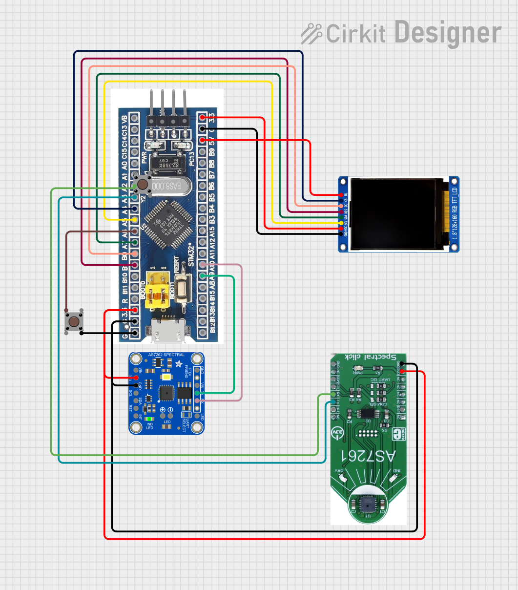 Open Project in Cirkit Designer
Explore Projects Built with ST7789V_WAVESHARE_LCD_320x240
Open Project in Cirkit DesignerOpen Project in Cirkit DesignerOpen Project in Cirkit DesignerOpen Project in Cirkit DesignerCommon Applications and Use Cases
- Portable devices and handheld systems
- IoT dashboards and smart home displays
- Industrial control panels
- Educational and hobbyist projects
- Wearable devices and smartwatches
- Arduino, Raspberry Pi, and other microcontroller-based projects
Technical Specifications
Below are the key technical details of the ST7789V_WAVESHARE_LCD_320x240 module:
| Parameter | Specification |
|---|---|
| Display Resolution | 320 x 240 pixels |
| Display Type | TFT LCD |
| Driver IC | ST7789V |
| Interface | SPI (4-wire) |
| Operating Voltage | 3.3V |
| Backlight Voltage | 3.0V - 3.3V |
| Power Consumption | Low power consumption |
| Viewing Angle | Wide viewing angle |
| Display Colors | 65K (16-bit RGB) |
| Module Dimensions | 52mm x 40mm |
| Active Area | 48.6mm x 36.4mm |
| Operating Temperature | -20°C to 70°C |
Pin Configuration and Descriptions
The module uses a 7-pin interface for communication and control. Below is the pinout:
| Pin | Name | Description |
|---|---|---|
| 1 | GND | Ground connection |
| 2 | VCC | Power supply (3.3V) |
| 3 | SCL | Serial Clock Line (SPI clock input) |
| 4 | SDA | Serial Data Line (SPI data input) |
| 5 | RES | Reset pin (active low) |
| 6 | DC | Data/Command control pin (High for data, Low for command) |
| 7 | BL | Backlight control (connect to 3.3V for always-on or use PWM for brightness control) |
Usage Instructions
How to Use the Component in a Circuit
- Power Supply: Connect the
VCCpin to a 3.3V power source and theGNDpin to ground. - SPI Communication: Connect the
SCLandSDApins to the SPI clock and data lines of your microcontroller, respectively. - Control Pins:
- Connect the
RESpin to a GPIO pin on your microcontroller for resetting the display. - Connect the
DCpin to another GPIO pin to toggle between data and command modes.
- Connect the
- Backlight: Connect the
BLpin to 3.3V for constant backlight or to a PWM-capable GPIO pin for brightness control. - Initialization: Use the appropriate initialization sequence for the ST7789V driver IC to configure the display.
Important Considerations and Best Practices
- Ensure the power supply voltage does not exceed 3.3V to avoid damaging the module.
- Use level shifters if your microcontroller operates at 5V logic levels.
- Keep SPI clock frequency within the module's supported range for reliable communication.
- Use decoupling capacitors near the power pins to reduce noise and improve stability.
- Handle the module carefully to avoid damaging the fragile LCD screen.
Example Code for Arduino UNO
Below is an example of how to interface the ST7789V_WAVESHARE_LCD_320x240 with an Arduino UNO using the Adafruit GFX and Adafruit ST7789 libraries:
#include <Adafruit_GFX.h>      // Core graphics library
#include <Adafruit_ST7789.h>   // ST7789 driver library
#include <SPI.h>

// Define pin connections
#define TFT_CS    10  // Chip select pin
#define TFT_RST   9   // Reset pin
#define TFT_DC    8   // Data/Command pin

// Initialize the display object
Adafruit_ST7789 tft = Adafruit_ST7789(TFT_CS, TFT_DC, TFT_RST);

void setup() {
  // Initialize serial communication for debugging
  Serial.begin(9600);
  Serial.println("ST7789V LCD Test");

  // Initialize the display
  tft.init(240, 320);  // Initialize with width=240, height=320
  tft.setRotation(1);  // Set display orientation (1 = landscape)

  // Fill the screen with a color
  tft.fillScreen(ST77XX_BLACK);

  // Draw some text
  tft.setTextColor(ST77XX_WHITE);
  tft.setTextSize(2);
  tft.setCursor(10, 10);
  tft.println("Hello, ST7789V!");
}

void loop() {
  // Add your main code here
}
Troubleshooting and FAQs
Common Issues and Solutions
No Display Output:
- Verify all connections, especially power and SPI lines.
- Ensure the
RESpin is properly connected and the reset sequence is executed. - Check the initialization code for compatibility with the ST7789V driver.
Flickering or Unstable Display:
- Reduce the SPI clock speed to improve communication stability.
- Use shorter wires to minimize signal interference.
Backlight Not Turning On:
- Ensure the
BLpin is connected to 3.3V or a PWM signal. - Check for loose connections or damaged backlight circuitry.
- Ensure the
Incorrect Colors or Graphics:
- Verify the color format (e.g., 16-bit RGB) used in the code matches the display's configuration.
- Ensure the
DCpin is toggled correctly between data and command modes.
FAQs
Q: Can I use this module with a 5V microcontroller?
A: Yes, but you must use level shifters to convert the 5V logic signals to 3.3V to avoid damaging the module.
Q: What is the maximum SPI clock speed supported?
A: The ST7789V typically supports SPI clock speeds up to 15 MHz, but this may vary depending on your specific setup.
Q: Can I control the backlight brightness?
A: Yes, you can use a PWM signal on the BL pin to adjust the brightness.
Q: Is this module compatible with Raspberry Pi?
A: Yes, the module can be used with Raspberry Pi via SPI, and libraries like luma.lcd or ST7789-python can be used for control.