Cirkit Designer Logo
Cirkit Designer
Your all-in-one circuit design IDE
Home / 
Component Documentation

How to Use SIM A7672S 4G LTE + 2G + GNSS Development Board – With GNSS: Examples, Pinouts, and Specs

Image of SIM A7672S 4G LTE + 2G + GNSS Development Board – With GNSS
Cirkit Designer LogoDesign with SIM A7672S 4G LTE + 2G + GNSS Development Board – With GNSS in Cirkit Designer

Introduction

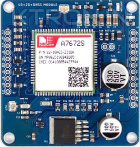
The SIM A7672S 4G LTE + 2G + GNSS Development Board is a versatile and powerful module designed for IoT applications. Manufactured under SKU: KSTM1548 with part ID: SIMA7672S, this development board integrates 4G LTE and 2G connectivity along with GNSS (Global Navigation Satellite System) capabilities. It is ideal for projects requiring reliable communication, location tracking, and navigation.

Explore Projects Built with SIM A7672S 4G LTE + 2G + GNSS Development Board – With GNSS

Use Cirkit Designer to design, explore, and prototype these projects online. Some projects support real-time simulation. Click "Open Project" to start designing instantly!
Lilygo 7670e-Based Smart Interface with LCD Display and Keypad
Image of Paower: A project utilizing SIM A7672S 4G LTE + 2G + GNSS Development Board – With GNSS in a practical application
This circuit features a Lilygo 7670e microcontroller interfaced with a 16x2 I2C LCD for display, a 4X4 membrane matrix keypad for input, and an arcade button for additional control. It also includes a 4G antenna and a GPS antenna for communication and location tracking capabilities.
Cirkit Designer LogoOpen Project in Cirkit Designer
Cellular-Enabled IoT Device with Real-Time Clock and Power Management
Image of LRCM PHASE 2 BASIC: A project utilizing SIM A7672S 4G LTE + 2G + GNSS Development Board – With GNSS in a practical application
This circuit features a LilyGo-SIM7000G module for cellular communication and GPS functionality, interfaced with an RTC DS3231 for real-time clock capabilities. It includes voltage sensing through two voltage sensor modules, and uses an 8-channel opto-coupler for isolating different parts of the circuit. Power management is handled by a buck converter connected to a DC power source and batteries, with a fuse for protection and a rocker switch for on/off control. Additionally, there's an LED for indication purposes.
Cirkit Designer LogoOpen Project in Cirkit Designer
ESP32-Based Cellular and GPS Tracking System with User Interface
Image of Keychain Device: A project utilizing SIM A7672S 4G LTE + 2G + GNSS Development Board – With GNSS in a practical application
This circuit features an ESP32 microcontroller interfaced with a SIM 800L GSM module for cellular communication and a Neo 6M GPS module for location tracking. A voltage regulator is used to maintain a stable voltage supply from a polymer lithium-ion battery to the GSM, GPS, and ESP32 modules. Additionally, the circuit includes a pushbutton to trigger inputs and an LED with a current-limiting resistor, likely for status indication.
Cirkit Designer LogoOpen Project in Cirkit Designer
Solar-Powered GSM/GPRS+GPS Tracker with Seeeduino XIAO
Image of SOS System : A project utilizing SIM A7672S 4G LTE + 2G + GNSS Development Board – With GNSS in a practical application
This circuit features an Ai Thinker A9G development board for GSM/GPRS and GPS/BDS connectivity, interfaced with a Seeeduino XIAO microcontroller for control and data processing. A solar cell, coupled with a TP4056 charging module, charges a 3.3V battery, which powers the system through a 3.3V regulator ensuring stable operation. The circuit likely serves for remote data communication and location tracking, with the capability to be powered by renewable energy and interfaced with additional sensors or input devices via the Seeeduino XIAO.
Cirkit Designer LogoOpen Project in Cirkit Designer

Explore Projects Built with SIM A7672S 4G LTE + 2G + GNSS Development Board – With GNSS

Use Cirkit Designer to design, explore, and prototype these projects online. Some projects support real-time simulation. Click "Open Project" to start designing instantly!
Image of Paower: A project utilizing SIM A7672S 4G LTE + 2G + GNSS Development Board – With GNSS in a practical application
Lilygo 7670e-Based Smart Interface with LCD Display and Keypad
This circuit features a Lilygo 7670e microcontroller interfaced with a 16x2 I2C LCD for display, a 4X4 membrane matrix keypad for input, and an arcade button for additional control. It also includes a 4G antenna and a GPS antenna for communication and location tracking capabilities.
Cirkit Designer LogoOpen Project in Cirkit Designer
Image of LRCM PHASE 2 BASIC: A project utilizing SIM A7672S 4G LTE + 2G + GNSS Development Board – With GNSS in a practical application
Cellular-Enabled IoT Device with Real-Time Clock and Power Management
This circuit features a LilyGo-SIM7000G module for cellular communication and GPS functionality, interfaced with an RTC DS3231 for real-time clock capabilities. It includes voltage sensing through two voltage sensor modules, and uses an 8-channel opto-coupler for isolating different parts of the circuit. Power management is handled by a buck converter connected to a DC power source and batteries, with a fuse for protection and a rocker switch for on/off control. Additionally, there's an LED for indication purposes.
Cirkit Designer LogoOpen Project in Cirkit Designer
Image of Keychain Device: A project utilizing SIM A7672S 4G LTE + 2G + GNSS Development Board – With GNSS in a practical application
ESP32-Based Cellular and GPS Tracking System with User Interface
This circuit features an ESP32 microcontroller interfaced with a SIM 800L GSM module for cellular communication and a Neo 6M GPS module for location tracking. A voltage regulator is used to maintain a stable voltage supply from a polymer lithium-ion battery to the GSM, GPS, and ESP32 modules. Additionally, the circuit includes a pushbutton to trigger inputs and an LED with a current-limiting resistor, likely for status indication.
Cirkit Designer LogoOpen Project in Cirkit Designer
Image of SOS System : A project utilizing SIM A7672S 4G LTE + 2G + GNSS Development Board – With GNSS in a practical application
Solar-Powered GSM/GPRS+GPS Tracker with Seeeduino XIAO
This circuit features an Ai Thinker A9G development board for GSM/GPRS and GPS/BDS connectivity, interfaced with a Seeeduino XIAO microcontroller for control and data processing. A solar cell, coupled with a TP4056 charging module, charges a 3.3V battery, which powers the system through a 3.3V regulator ensuring stable operation. The circuit likely serves for remote data communication and location tracking, with the capability to be powered by renewable energy and interfaced with additional sensors or input devices via the Seeeduino XIAO.
Cirkit Designer LogoOpen Project in Cirkit Designer

Common Applications and Use Cases

  • IoT Devices: Smart meters, industrial monitoring, and remote sensors.
  • Asset Tracking: Real-time location tracking for vehicles, goods, or equipment.
  • Navigation Systems: GNSS-based navigation for drones, robots, and vehicles.
  • Smart Agriculture: Remote monitoring and control of agricultural equipment.
  • Emergency Systems: Communication and location tracking in disaster management.

Technical Specifications

Key Technical Details

Parameter Specification
Module SIM A7672S
Cellular Connectivity 4G LTE, 2G
GNSS Support GPS, GLONASS, BeiDou, Galileo, QZSS
Operating Voltage 3.4V to 4.2V (Typical: 3.8V)
Power Consumption Idle: ~1.5mA, Active (LTE): ~500mA, Peak: ~2A
Communication Interfaces UART, USB 2.0, GPIO, I2C, SPI
Operating Temperature -40°C to +85°C
Dimensions 30mm x 30mm x 2.9mm
Antenna Interfaces LTE Main, LTE Diversity, GNSS
Certifications CE, FCC, RoHS

Pin Configuration and Descriptions

Pin Name Pin Number Description
VCC 1 Power supply input (3.4V to 4.2V)
GND 2 Ground connection
TXD 3 UART Transmit Data
RXD 4 UART Receive Data
USB_D+ 5 USB Data Positive
USB_D- 6 USB Data Negative
GNSS_TXD 7 GNSS UART Transmit Data
GNSS_RXD 8 GNSS UART Receive Data
GPIO1 9 General Purpose Input/Output 1
GPIO2 10 General Purpose Input/Output 2
RESET 11 Reset pin (active low)
PWRKEY 12 Power key to turn the module on/off
ANT_MAIN 13 Main LTE antenna interface
ANT_DIV 14 LTE diversity antenna interface
ANT_GNSS 15 GNSS antenna interface

Usage Instructions

How to Use the Component in a Circuit

  1. Power Supply: Connect the VCC pin to a regulated 3.8V power source and GND to ground.
  2. Antenna Connections: Attach appropriate antennas to the ANT_MAIN, ANT_DIV, and ANT_GNSS interfaces for LTE and GNSS functionality.
  3. UART Communication: Use the TXD and RXD pins to communicate with a microcontroller or PC via UART.
  4. USB Interface: Connect USB_D+ and USB_D- to a USB host for data communication or firmware updates.
  5. Power Control: Use the PWRKEY pin to turn the module on or off. Pull the pin low for at least 1 second to power on the module.
  6. GNSS Functionality: Use the GNSS_TXD and GNSS_RXD pins to receive GNSS data.

Important Considerations and Best Practices

  • Power Supply: Ensure the power supply can handle peak currents of up to 2A to avoid instability.
  • Antenna Placement: Place antennas away from noisy components to improve signal quality.
  • Heat Management: If operating in high-temperature environments, consider adding heat dissipation measures.
  • Firmware Updates: Regularly update the module firmware to ensure compatibility and performance.

Example: Connecting to an Arduino UNO

Below is an example of how to interface the SIM A7672S module with an Arduino UNO for basic communication:

Circuit Connections

SIM A7672S Pin Arduino UNO Pin
TXD RX (Pin 0)
RXD TX (Pin 1)
GND GND
VCC External 3.8V

Arduino Code

#include <SoftwareSerial.h>

// Define RX and TX pins for SoftwareSerial
SoftwareSerial simModule(10, 11); // RX = Pin 10, TX = Pin 11

void setup() {
  // Initialize serial communication with the module and the PC
  Serial.begin(9600); // Communication with PC
  simModule.begin(9600); // Communication with SIM A7672S module

  Serial.println("Initializing SIM A7672S module...");
  delay(1000);

  // Send an AT command to check communication
  simModule.println("AT");
}

void loop() {
  // Check for data from the module
  if (simModule.available()) {
    String response = simModule.readString();
    Serial.println("Module Response: " + response);
  }

  // Check for data from the PC
  if (Serial.available()) {
    String command = Serial.readString();
    simModule.println(command); // Send command to the module
  }
}

Troubleshooting and FAQs

Common Issues and Solutions

  1. Module Not Powering On

    • Cause: Insufficient power supply.
    • Solution: Ensure the power source provides a stable 3.8V and can handle peak currents of 2A.
  2. No Response to AT Commands

    • Cause: Incorrect UART connections or baud rate.
    • Solution: Verify TXD and RXD connections and ensure the baud rate matches the module's default (9600 bps).
  3. Poor GNSS Signal

    • Cause: Antenna placement or environmental interference.
    • Solution: Place the GNSS antenna in an open area with a clear view of the sky.
  4. Intermittent LTE Connectivity

    • Cause: Weak signal or improper antenna connection.
    • Solution: Check the LTE antenna connection and ensure the module is in an area with good network coverage.

FAQs

  1. Can the module operate on 5V?

    • No, the module requires a power supply between 3.4V and 4.2V. Exceeding this range may damage the module.
  2. What is the maximum baud rate supported?

    • The module supports baud rates up to 115200 bps.
  3. Does the module support SMS and voice calls?

    • Yes, the SIM A7672S module supports SMS, voice calls, and data communication.
  4. Can I use the module without an external microcontroller?

    • Yes, the module can be controlled via a PC using a USB-to-UART adapter.

By following this documentation, users can effectively integrate the SIM A7672S module into their projects and troubleshoot common issues.