How to Use Power Monitoring HAT: Examples, Pinouts, and Specs
Introduction
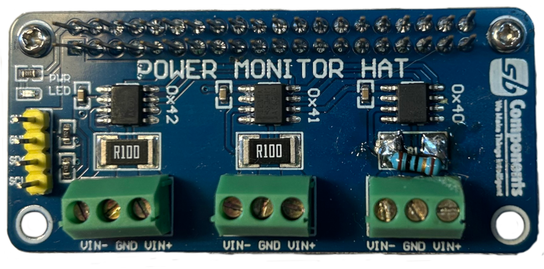
The Power Monitoring HAT by SB Components is an add-on board designed for the Raspberry Pi. It allows users to monitor power consumption, voltage levels, and current in real-time. This HAT is ideal for energy management, optimization, and monitoring applications in IoT, robotics, and other electronics projects. By providing accurate power data, it helps users design more efficient systems and troubleshoot power-related issues effectively.
Explore Projects Built with Power Monitoring HAT

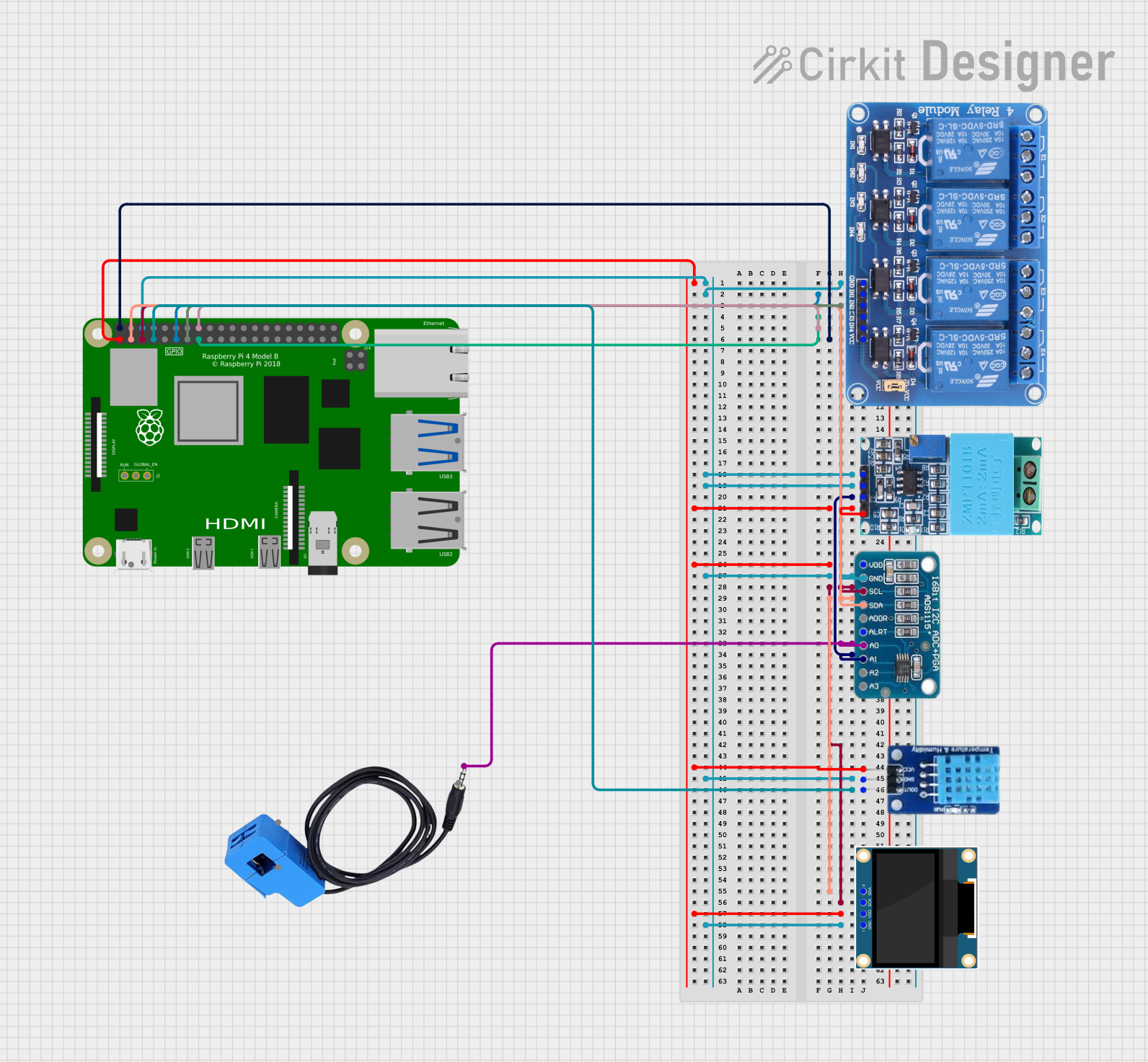

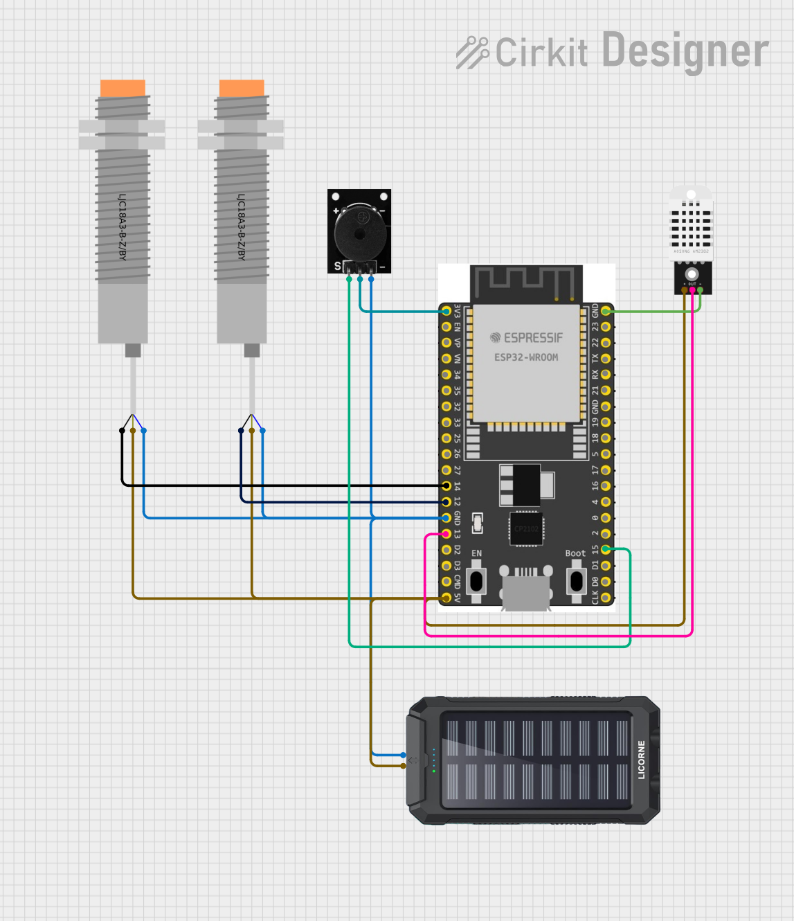
Explore Projects Built with Power Monitoring HAT
Common Applications and Use Cases
- Monitoring power consumption in IoT devices
- Energy optimization in robotics and automation systems
- Real-time voltage and current tracking for battery-powered projects
- Power diagnostics and troubleshooting in embedded systems
- Educational projects for learning about power management
Technical Specifications
The Power Monitoring HAT is equipped with advanced sensors and interfaces to provide precise power measurements. Below are the key technical details:
Key Specifications
| Parameter | Value |
|---|---|
| Input Voltage Range | 3.3V to 5V |
| Current Measurement | 0A to 3A |
| Voltage Measurement | 0V to 26V |
| Communication Protocol | I2C |
| Operating Temperature | -40°C to 85°C |
| Dimensions | 65mm x 56mm x 15mm |
| Compatibility | Raspberry Pi 3, 4, and Zero |
Pin Configuration and Descriptions
The Power Monitoring HAT connects to the Raspberry Pi via the GPIO header. Below is the pin configuration:
| Pin Number | Pin Name | Description |
|---|---|---|
| 1 | 3.3V | Power supply for the HAT |
| 3 | SDA | I2C data line |
| 5 | SCL | I2C clock line |
| 6 | GND | Ground connection |
| 7 | ALERT | Interrupt pin for alerts (optional use) |
| 8 | V+ | Voltage input for monitoring |
| 10 | I+ | Current input for monitoring |
Usage Instructions
How to Use the Power Monitoring HAT in a Circuit
- Attach the HAT: Securely connect the Power Monitoring HAT to the GPIO header of your Raspberry Pi.
- Connect Power Source: Connect the voltage and current inputs (V+ and I+) to the power source or load you want to monitor.
- Enable I2C: Ensure that the I2C interface is enabled on your Raspberry Pi. You can enable it via
raspi-config:- Run
sudo raspi-config. - Navigate to
Interfacing Options > I2Cand enable it.
- Run
- Install Required Libraries: Install the necessary Python libraries for I2C communication and power monitoring. For example:
sudo apt-get update sudo apt-get install python3-smbus python3-pip pip3 install adafruit-circuitpython-ina219 - Run the Code: Use the sample Python code below to read voltage, current, and power data.
Sample Code for Raspberry Pi
import time
from adafruit_ina219 import INA219
from smbus2 import SMBus
Initialize I2C bus and INA219 sensor
i2c_bus = SMBus(1) # Use I2C bus 1 on Raspberry Pi ina219 = INA219(i2c_bus)
Function to read and display power data
def read_power_data(): try: voltage = ina219.bus_voltage # Read bus voltage in volts current = ina219.current / 1000 # Convert current to amps power = ina219.power # Power in milliwatts
    print(f"Voltage: {voltage:.2f} V")
    print(f"Current: {current:.3f} A")
    print(f"Power: {power:.2f} mW")
except Exception as e:
    print(f"Error reading data: {e}")
Main loop to continuously read data
while True: read_power_data() time.sleep(1) # Wait 1 second before the next reading
Important Considerations and Best Practices
- Voltage and Current Limits: Ensure that the input voltage and current do not exceed the HAT's rated limits (26V and 3A, respectively).
- Secure Connections: Use proper connectors and cables to avoid loose connections, which can lead to inaccurate readings or damage.
- I2C Address Conflicts: If using multiple I2C devices, ensure that their addresses do not conflict. The default I2C address for the HAT is
0x40. - Power Supply: Use a stable power supply for the Raspberry Pi to avoid fluctuations in readings.
Troubleshooting and FAQs
Common Issues and Solutions
No Data or Incorrect Readings
- Cause: I2C interface not enabled or misconfigured.
- Solution: Verify that I2C is enabled using
raspi-config. Check the wiring and ensure proper connections.
I2C Address Not Detected
- Cause: Address conflict or incorrect wiring.
- Solution: Use the
i2cdetectcommand to scan for connected devices:sudo apt-get install i2c-tools i2cdetect -y 10x40by default).
Overheating or Damage
- Cause: Exceeding voltage or current limits.
- Solution: Double-check the input voltage and current. Use a multimeter to verify the values before connecting.
Python Library Errors
- Cause: Missing or outdated libraries.
- Solution: Reinstall the required libraries using:
pip3 install --upgrade adafruit-circuitpython-ina219
FAQs
Q1: Can I use the Power Monitoring HAT with other microcontrollers?
A1: Yes, the HAT can be used with other microcontrollers that support I2C communication, such as Arduino. However, you may need to adapt the code accordingly.
Q2: What is the accuracy of the measurements?
A2: The HAT provides high accuracy for voltage, current, and power measurements, typically within ±1%.
Q3: Can I monitor both DC and AC power?
A3: The HAT is designed for DC power monitoring only. It is not suitable for AC power measurements.
Q4: How can I change the I2C address of the HAT?
A4: The I2C address can be changed by modifying the onboard address jumpers. Refer to the HAT's datasheet for detailed instructions.
This concludes the documentation for the Power Monitoring HAT by SB Components. For further assistance, refer to the official product manual or contact SB Components support.