Cirkit Designer Logo
Cirkit Designer
Your all-in-one circuit design IDE
Home / 
Component Documentation

How to Use ESP32 (30 pin) back: Examples, Pinouts, and Specs

Image of ESP32 (30 pin) back
Cirkit Designer LogoDesign with ESP32 (30 pin) back in Cirkit Designer

Introduction

The ESP32 is a powerful microcontroller developed by Espressif Systems, featuring integrated Wi-Fi and Bluetooth capabilities. With its 30-pin configuration, the ESP32 is designed to support a wide range of input/output functions, making it an excellent choice for Internet of Things (IoT) applications, smart devices, and embedded systems. Its high processing power, low energy consumption, and versatile connectivity options make it a popular choice among hobbyists and professionals alike.

Explore Projects Built with ESP32 (30 pin) back

Use Cirkit Designer to design, explore, and prototype these projects online. Some projects support real-time simulation. Click "Open Project" to start designing instantly!
ESP32-Based Smart Display with Camera and Audio Alert System
Image of cam_circuit_design: A project utilizing ESP32 (30 pin) back in a practical application
This circuit features two ESP32 microcontrollers, one standard 30-pin version and one ESP32-CAM module, both sharing a common ground and power supply. The 30-pin ESP32 is interfaced with an I2C LCD 16x2 Screen for display purposes, using its I2C pins (D21 for SDA and D22 for SCL), and controls a buzzer connected to pin D23. Additionally, the ESP32-CAM is connected to the 30-pin ESP32 via serial communication through pins TX2 and RX2 for potential image data transfer.
Cirkit Designer LogoOpen Project in Cirkit Designer
ESP32-Based OLED Display Interface
Image of d: A project utilizing ESP32 (30 pin) back in a practical application
This circuit features an ESP32 microcontroller connected to an OLED 1.3" display. The ESP32's GPIO pins 21 and 22 are used for I2C communication (SDA and SCL respectively) with the OLED display. The display is powered by the 5V output from the ESP32, and both devices share a common ground.
Cirkit Designer LogoOpen Project in Cirkit Designer
Battery-Powered ESP32 Data Logger with Oscilloscope Monitoring
Image of electromiografia: A project utilizing ESP32 (30 pin) back in a practical application
This circuit features an ESP32 microcontroller powered by a 7V battery, with its ground connected to a common ground. The ESP32's D35 pin is monitored by a mixed signal oscilloscope, and an alligator clip cable is used to connect the oscilloscope's second channel to the common ground.
Cirkit Designer LogoOpen Project in Cirkit Designer
ESP32-Based Environmental Monitoring System with OLED Display
Image of esproj: A project utilizing ESP32 (30 pin) back in a practical application
This circuit features an ESP32 microcontroller as the central processing unit, interfacing with a DHT11 temperature and humidity sensor, an MPU-6050 accelerometer and gyroscope, an OLED display, and a separate temperature sensor. The ESP32 communicates with the MPU-6050 and the OLED display via I2C (using pins D22 and D21 for SCL and SDA, respectively), reads temperature data from the DHT11 sensor through pin D18, and interfaces with the additional temperature sensor via pin D5. All components share a common power supply connected to the ESP32's Vin pin and a common ground.
Cirkit Designer LogoOpen Project in Cirkit Designer

Explore Projects Built with ESP32 (30 pin) back

Use Cirkit Designer to design, explore, and prototype these projects online. Some projects support real-time simulation. Click "Open Project" to start designing instantly!
Image of cam_circuit_design: A project utilizing ESP32 (30 pin) back in a practical application
ESP32-Based Smart Display with Camera and Audio Alert System
This circuit features two ESP32 microcontrollers, one standard 30-pin version and one ESP32-CAM module, both sharing a common ground and power supply. The 30-pin ESP32 is interfaced with an I2C LCD 16x2 Screen for display purposes, using its I2C pins (D21 for SDA and D22 for SCL), and controls a buzzer connected to pin D23. Additionally, the ESP32-CAM is connected to the 30-pin ESP32 via serial communication through pins TX2 and RX2 for potential image data transfer.
Cirkit Designer LogoOpen Project in Cirkit Designer
Image of d: A project utilizing ESP32 (30 pin) back in a practical application
ESP32-Based OLED Display Interface
This circuit features an ESP32 microcontroller connected to an OLED 1.3" display. The ESP32's GPIO pins 21 and 22 are used for I2C communication (SDA and SCL respectively) with the OLED display. The display is powered by the 5V output from the ESP32, and both devices share a common ground.
Cirkit Designer LogoOpen Project in Cirkit Designer
Image of electromiografia: A project utilizing ESP32 (30 pin) back in a practical application
Battery-Powered ESP32 Data Logger with Oscilloscope Monitoring
This circuit features an ESP32 microcontroller powered by a 7V battery, with its ground connected to a common ground. The ESP32's D35 pin is monitored by a mixed signal oscilloscope, and an alligator clip cable is used to connect the oscilloscope's second channel to the common ground.
Cirkit Designer LogoOpen Project in Cirkit Designer
Image of esproj: A project utilizing ESP32 (30 pin) back in a practical application
ESP32-Based Environmental Monitoring System with OLED Display
This circuit features an ESP32 microcontroller as the central processing unit, interfacing with a DHT11 temperature and humidity sensor, an MPU-6050 accelerometer and gyroscope, an OLED display, and a separate temperature sensor. The ESP32 communicates with the MPU-6050 and the OLED display via I2C (using pins D22 and D21 for SCL and SDA, respectively), reads temperature data from the DHT11 sensor through pin D18, and interfaces with the additional temperature sensor via pin D5. All components share a common power supply connected to the ESP32's Vin pin and a common ground.
Cirkit Designer LogoOpen Project in Cirkit Designer

Common Applications and Use Cases

  • IoT devices and smart home automation
  • Wireless sensor networks
  • Wearable technology
  • Robotics and drones
  • Industrial automation
  • Real-time data monitoring and logging

Technical Specifications

The ESP32 (30-pin variant) is equipped with robust hardware and versatile features. Below are its key technical specifications:

Key Technical Details

  • Microcontroller: Tensilica Xtensa LX6 dual-core processor
  • Clock Speed: Up to 240 MHz
  • Flash Memory: 4 MB (varies by model)
  • SRAM: 520 KB
  • Wi-Fi: 802.11 b/g/n
  • Bluetooth: v4.2 BR/EDR and BLE
  • Operating Voltage: 3.3V
  • Input Voltage Range: 5V (via USB) or 3.3V (via VIN pin)
  • GPIO Pins: 30 pins (multipurpose)
  • ADC Channels: 18 (12-bit resolution)
  • DAC Channels: 2
  • PWM Outputs: 16
  • I2C Interfaces: 2
  • SPI Interfaces: 4
  • UART Interfaces: 3
  • Power Consumption: Ultra-low power consumption in deep sleep mode (~10 µA)

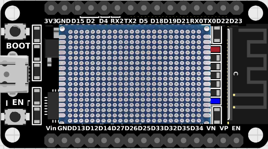
Pin Configuration and Descriptions

The ESP32 (30-pin variant) has a standard pinout. Below is a table describing the pin configuration:

Pin Number Pin Name Function
1 EN Enable pin (active high)
2 IO1 GPIO1, UART TX
3 IO3 GPIO3, UART RX
4 IO4 GPIO4, PWM, ADC
5 IO5 GPIO5, PWM, ADC
6 GND Ground
7 IO12 GPIO12, ADC, Touch Sensor
8 IO13 GPIO13, ADC, Touch Sensor
9 IO14 GPIO14, PWM, ADC
10 IO15 GPIO15, PWM, ADC
11 IO16 GPIO16, UART RX2
12 IO17 GPIO17, UART TX2
13 IO18 GPIO18, SPI CLK
14 IO19 GPIO19, SPI MISO
15 IO21 GPIO21, I2C SDA
16 IO22 GPIO22, I2C SCL
17 IO23 GPIO23, SPI MOSI
18 VIN Input voltage (3.3V or 5V)
19 3V3 3.3V output
20 GND Ground
21 IO25 GPIO25, DAC1
22 IO26 GPIO26, DAC2
23 IO27 GPIO27, ADC, Touch Sensor
24 IO32 GPIO32, ADC, Touch Sensor
25 IO33 GPIO33, ADC, Touch Sensor
26 IO34 GPIO34, ADC (input only)
27 IO35 GPIO35, ADC (input only)
28 IO36 GPIO36, ADC (input only)
29 IO39 GPIO39, ADC (input only)
30 GND Ground

Usage Instructions

How to Use the ESP32 in a Circuit

  1. Powering the ESP32:

    • Use a USB cable to power the ESP32 via the micro-USB port (5V input).
    • Alternatively, supply 3.3V directly to the VIN pin. Ensure the power source is stable.
  2. Connecting Peripherals:

    • Use GPIO pins for digital input/output.
    • Connect sensors to ADC pins for analog input.
    • Use I2C (SDA, SCL) or SPI (MOSI, MISO, CLK) for communication with external devices.
  3. Programming the ESP32:

    • Install the ESP32 board package in the Arduino IDE.
    • Connect the ESP32 to your computer via USB.
    • Select the correct board and port in the Arduino IDE.
    • Write and upload your code.

Important Considerations and Best Practices

  • Always use a level shifter when interfacing 5V devices with the ESP32 (3.3V logic).
  • Avoid drawing excessive current from GPIO pins (max 12 mA per pin).
  • Use pull-up or pull-down resistors for stable input signals.
  • Ensure proper grounding to avoid noise and interference.
  • Use deep sleep mode to conserve power in battery-powered applications.

Example Code for Arduino UNO Integration

Below is an example of how to blink an LED connected to GPIO2 of the ESP32:

// Example: Blink an LED connected to GPIO2 of the ESP32

// Define the GPIO pin for the LED
#define LED_PIN 2

void setup() {
  pinMode(LED_PIN, OUTPUT); // Set GPIO2 as an output pin
}

void loop() {
  digitalWrite(LED_PIN, HIGH); // Turn the LED on
  delay(1000);                 // Wait for 1 second
  digitalWrite(LED_PIN, LOW);  // Turn the LED off
  delay(1000);                 // Wait for 1 second
}

Troubleshooting and FAQs

Common Issues and Solutions

  1. ESP32 Not Detected by Computer:

    • Ensure the USB cable is functional and supports data transfer.
    • Install the correct USB-to-serial driver (e.g., CP2102 or CH340).
  2. Upload Fails in Arduino IDE:

    • Check the selected board and port in the Arduino IDE.
    • Press and hold the "BOOT" button on the ESP32 while uploading.
  3. Wi-Fi Connection Issues:

    • Verify the SSID and password in your code.
    • Ensure the Wi-Fi network is within range.
  4. Random Resets or Instability:

    • Check the power supply for stability.
    • Avoid drawing excessive current from GPIO pins.

FAQs

  • Q: Can the ESP32 operate on 5V logic?
    A: No, the ESP32 operates on 3.3V logic. Use level shifters for 5V devices.

  • Q: How do I reset the ESP32?
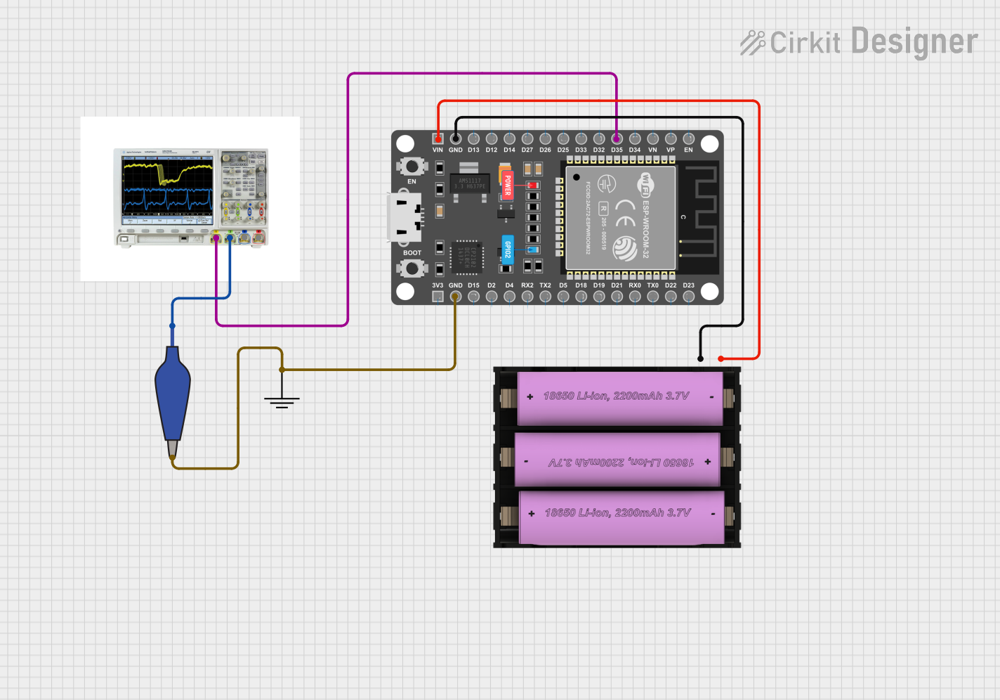
    A: Press the "EN" button on the board to reset the ESP32.

  • Q: Can I use the ESP32 with a battery?
    A: Yes, you can power the ESP32 using a 3.7V LiPo battery connected to the VIN pin.

This concludes the documentation for the ESP32 (30-pin variant).