How to Use Gravity: Analog Heart Rate Monitor Sensor (ECG): Examples, Pinouts, and Specs
Introduction
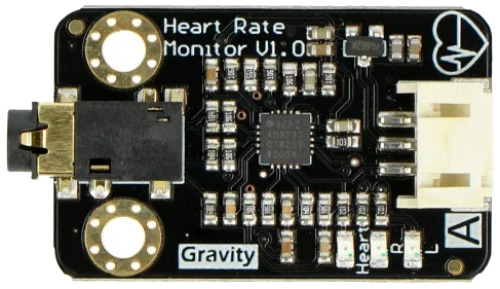
The Gravity: Analog Heart Rate Monitor Sensor (ECG), manufactured by DFRobot (Part ID: SEN0213), is a versatile sensor designed to measure the electrical activity of the heart. It provides real-time heart rate data through an analog output, making it ideal for applications in health monitoring, fitness tracking, and biofeedback systems. This sensor is easy to integrate into microcontroller-based projects, such as those using Arduino, due to its simple interface and compatibility with the Gravity series.
Explore Projects Built with Gravity: Analog Heart Rate Monitor Sensor (ECG)
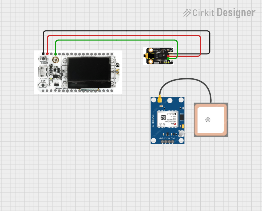

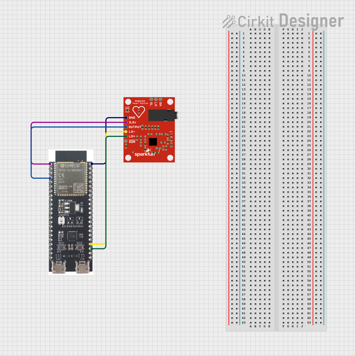
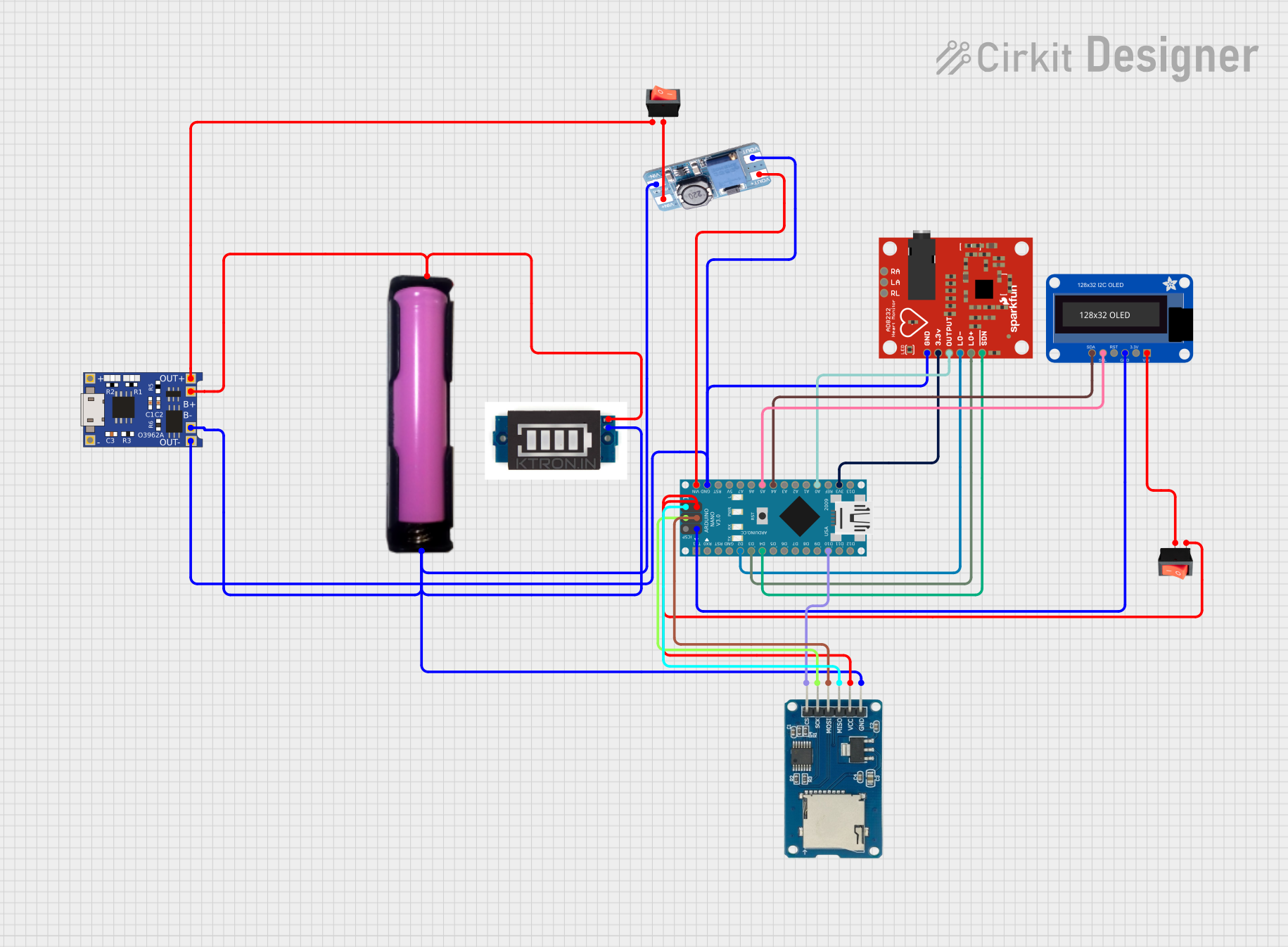
Explore Projects Built with Gravity: Analog Heart Rate Monitor Sensor (ECG)
Common Applications
- Personal health monitoring systems
- Fitness trackers
- Biofeedback devices
- Educational and research projects in biomedical engineering
- Heart rate-based control systems
Technical Specifications
Below are the key technical details and pin configuration for the Gravity: Analog Heart Rate Monitor Sensor (ECG):
Key Technical Details
| Parameter | Value |
|---|---|
| Operating Voltage | 3.3V to 5.5V |
| Output Signal | Analog |
| Output Voltage Range | 0V to 3.3V |
| Operating Current | < 10mA |
| Measurement Range | 0 to 100 beats per minute (BPM) |
| Interface Type | Gravity 3-pin interface |
| Dimensions | 35mm x 22mm |
| Weight | 7g |
Pin Configuration
| Pin Name | Description |
|---|---|
| VCC | Power supply input (3.3V to 5.5V) |
| GND | Ground connection |
| SIG | Analog signal output representing heart activity |
Usage Instructions
How to Use the Sensor in a Circuit
Connect the Sensor:
- Connect the VCC pin to the 5V (or 3.3V) power supply of your microcontroller.
- Connect the GND pin to the ground of your microcontroller.
- Connect the SIG pin to an analog input pin on your microcontroller (e.g., A0 on an Arduino UNO).
Attach the Electrodes:
- Place the included electrodes on the subject's chest or arms as per the instructions provided with the sensor.
- Connect the electrode cables to the sensor module.
Read the Analog Signal:
- The sensor outputs an analog voltage signal proportional to the heart's electrical activity. This signal can be read using the analog input of a microcontroller.
Process the Signal:
- Use a microcontroller to process the analog signal and extract heart rate data. You can use libraries or write custom code to calculate beats per minute (BPM).
Important Considerations and Best Practices
- Ensure the electrodes are properly attached to the skin for accurate readings.
- Avoid placing the sensor near strong electromagnetic interference (e.g., motors or Wi-Fi routers).
- Use a stable power supply to minimize noise in the analog signal.
- For best results, keep the subject relaxed and still during measurements.
Example Code for Arduino UNO
Below is an example code snippet to read and process the sensor's output using an Arduino UNO:
// Include necessary libraries
const int sensorPin = A0; // Analog pin connected to SIG pin of the sensor
int sensorValue = 0;      // Variable to store the analog reading

void setup() {
  Serial.begin(9600); // Initialize serial communication at 9600 baud
  pinMode(sensorPin, INPUT); // Set the sensor pin as input
}

void loop() {
  // Read the analog value from the sensor
  sensorValue = analogRead(sensorPin);

  // Convert the analog value to voltage (assuming 5V reference)
  float voltage = sensorValue * (5.0 / 1023.0);

  // Print the raw sensor value and voltage to the Serial Monitor
  Serial.print("Raw Value: ");
  Serial.print(sensorValue);
  Serial.print(" | Voltage: ");
  Serial.println(voltage);

  delay(100); // Delay for 100ms before the next reading
}
Notes:
- The above code reads the raw analog signal and converts it to voltage. To calculate BPM, additional signal processing (e.g., peak detection) is required.
- Use libraries like PulseSensor Playground or write custom algorithms for BPM calculation.
Troubleshooting and FAQs
Common Issues and Solutions
| Issue | Solution |
|---|---|
| No output signal | - Check all connections (VCC, GND, SIG). |
| - Ensure the sensor is powered (3.3V to 5.5V). | |
| - Verify that the electrodes are properly attached to the skin. | |
| High noise in the signal | - Ensure the subject is still and relaxed. |
| - Use shielded cables to reduce electromagnetic interference. | |
| - Check for a stable power supply. | |
| Incorrect or fluctuating BPM values | - Verify electrode placement and skin contact. |
| - Use signal filtering techniques in your code to smooth the data. |
FAQs
Can this sensor be used with a 3.3V microcontroller?
- Yes, the sensor operates within a voltage range of 3.3V to 5.5V, making it compatible with 3.3V systems.
How do I calculate BPM from the analog signal?
- You can calculate BPM by detecting peaks in the analog signal that correspond to heartbeats. Use libraries or write custom code for peak detection.
Can this sensor be used for medical-grade applications?
- No, this sensor is intended for educational and hobbyist purposes only. It is not certified for medical use.
What is the recommended placement for the electrodes?
- The electrodes should be placed on the chest or arms as per the instructions provided with the sensor for optimal signal quality.
By following this documentation, you can effectively integrate the Gravity: Analog Heart Rate Monitor Sensor (ECG) into your projects and troubleshoot common issues.