How to Use MPU-9250/6500/9255: Examples, Pinouts, and Specs
Introduction
The MPU-9250/6500/9255 is a highly integrated 9-axis motion tracking device that combines a 3-axis gyroscope, a 3-axis accelerometer, and a 3-axis magnetometer in a single compact package. This component is widely used for applications requiring precise orientation, motion detection, and spatial awareness. Its small size, low power consumption, and high performance make it ideal for use in robotics, drones, mobile devices, gaming controllers, and wearable technology.
Explore Projects Built with MPU-9250/6500/9255

Explore Projects Built with MPU-9250/6500/9255
Common Applications:
- Robotics for motion tracking and navigation
- Drones for stabilization and orientation control
- Mobile devices for gesture recognition and augmented reality
- Wearable devices for fitness tracking and activity monitoring
- Gaming controllers for motion-based input
Technical Specifications
Key Technical Details:
| Parameter | Value |
|---|---|
| Gyroscope Range | ±250, ±500, ±1000, ±2000 °/s |
| Accelerometer Range | ±2g, ±4g, ±8g, ±16g |
| Magnetometer Range | ±4800 µT |
| Operating Voltage | 2.4V to 3.6V |
| Communication Interface | I2C (up to 400 kHz) / SPI (up to 1 MHz) |
| Operating Temperature | -40°C to +85°C |
| Power Consumption | ~3.9 mA (full operation) |
| Package Dimensions | 3x3x1 mm (QFN package) |
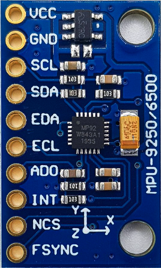
Pin Configuration and Descriptions:
MPU-9250/6500/9255 Pinout:
| Pin Number | Pin Name | Description |
|---|---|---|
| 1 | VDD | Power supply input (2.4V to 3.6V) |
| 2 | VDDIO | I/O voltage reference |
| 3 | GND | Ground |
| 4 | SCL | I2C clock input / SPI clock input |
| 5 | SDA/SDI | I2C data input/output / SPI data input |
| 6 | AD0/SDO | I2C address select / SPI data output |
| 7 | INT | Interrupt signal output |
| 8 | NCS | SPI chip select (active low) |
Usage Instructions
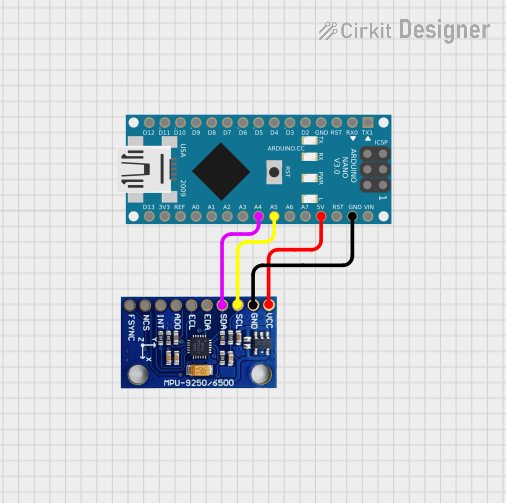
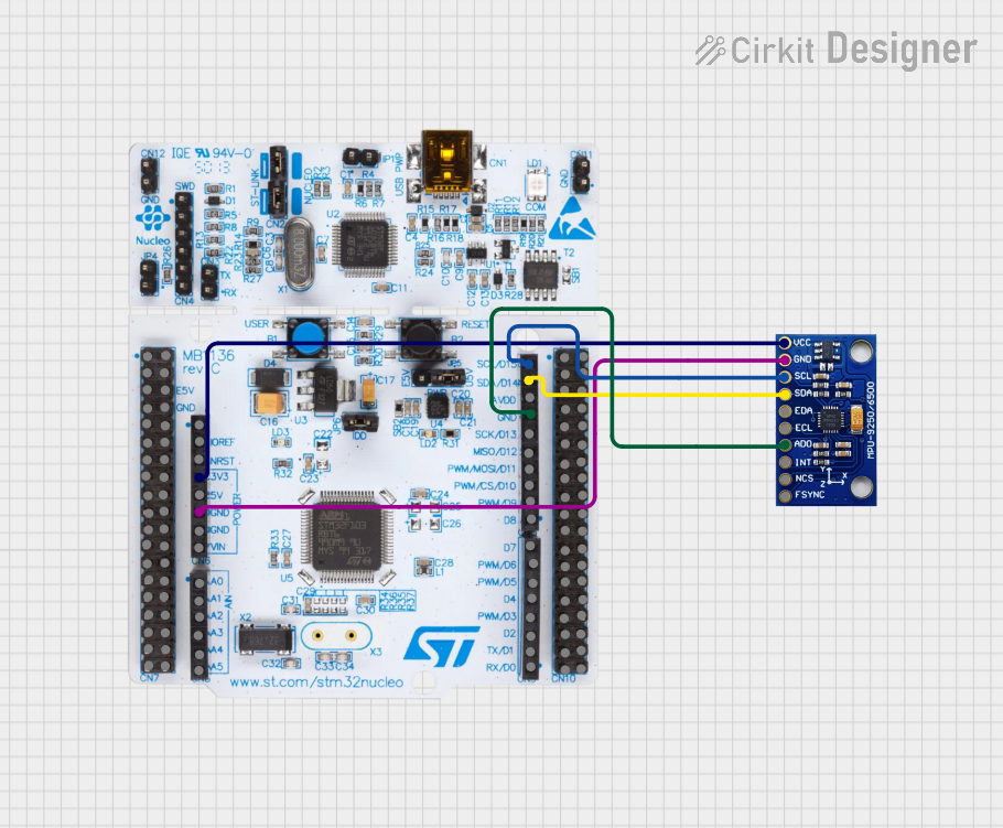
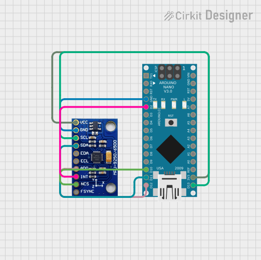
How to Use the MPU-9250/6500/9255 in a Circuit:
- Power Supply: Connect the VDD pin to a 3.3V power source and the GND pin to ground. Ensure the VDDIO pin matches the logic level of your microcontroller (e.g., 3.3V or 5V).
- Communication Interface: Choose between I2C or SPI communication:
- For I2C, connect the SCL and SDA pins to the corresponding I2C pins on your microcontroller. Use pull-up resistors (typically 4.7kΩ) on both lines.
- For SPI, connect the SCL, SDA/SDI, AD0/SDO, and NCS pins to the appropriate SPI pins on your microcontroller.
- Interrupt Pin: Optionally, connect the INT pin to a GPIO pin on your microcontroller to handle interrupts for motion events.
- Magnetometer: The magnetometer is accessed via a secondary I2C bus within the MPU-9250/9255. Ensure proper initialization in your code.
Important Considerations and Best Practices:
- Bypass Capacitors: Place a 0.1µF decoupling capacitor close to the VDD pin to reduce noise.
- I2C Address: The I2C address is determined by the AD0 pin. Connect AD0 to GND for address
0x68or to VDD for address0x69. - Calibration: Perform gyroscope, accelerometer, and magnetometer calibration for accurate measurements.
- Mounting Orientation: Ensure the device is mounted securely and aligned with your system's coordinate axes.
Example Code for Arduino UNO:
Below is an example of how to interface the MPU-9250 with an Arduino UNO using I2C:
#include <Wire.h>

// MPU-9250 I2C address (default is 0x68 if AD0 is connected to GND)
#define MPU9250_ADDRESS 0x68

void setup() {
  Wire.begin(); // Initialize I2C communication
  Serial.begin(9600); // Initialize serial communication for debugging

  // Wake up the MPU-9250
  Wire.beginTransmission(MPU9250_ADDRESS);
  Wire.write(0x6B); // Power management register
  Wire.write(0x00); // Set to zero to wake up the sensor
  Wire.endTransmission();

  // Configure gyroscope (±250 °/s)
  Wire.beginTransmission(MPU9250_ADDRESS);
  Wire.write(0x1B); // Gyroscope configuration register
  Wire.write(0x00); // Set full scale range to ±250 °/s
  Wire.endTransmission();

  // Configure accelerometer (±2g)
  Wire.beginTransmission(MPU9250_ADDRESS);
  Wire.write(0x1C); // Accelerometer configuration register
  Wire.write(0x00); // Set full scale range to ±2g
  Wire.endTransmission();
}

void loop() {
  // Read accelerometer data
  Wire.beginTransmission(MPU9250_ADDRESS);
  Wire.write(0x3B); // Starting register for accelerometer data
  Wire.endTransmission(false);
  Wire.requestFrom(MPU9250_ADDRESS, 6); // Request 6 bytes (X, Y, Z)

  if (Wire.available() == 6) {
    int16_t accelX = (Wire.read() << 8) | Wire.read();
    int16_t accelY = (Wire.read() << 8) | Wire.read();
    int16_t accelZ = (Wire.read() << 8) | Wire.read();

    // Print accelerometer data
    Serial.print("Accel X: "); Serial.print(accelX);
    Serial.print(" | Accel Y: "); Serial.print(accelY);
    Serial.print(" | Accel Z: "); Serial.println(accelZ);
  }

  delay(500); // Delay for readability
}
Troubleshooting and FAQs
Common Issues:
No Communication with the Sensor:
- Ensure the correct I2C address (
0x68or0x69) is used in your code. - Verify pull-up resistors are connected to the I2C lines.
- Check wiring for loose or incorrect connections.
- Ensure the correct I2C address (
Incorrect or No Data Output:
- Confirm the sensor is properly powered (check VDD and GND connections).
- Ensure the sensor is initialized correctly in your code.
- Perform calibration to eliminate offsets and inaccuracies.
Magnetometer Not Responding:
- Verify the secondary I2C bus is initialized in your code.
- Check for interference from nearby magnetic sources.
Tips for Troubleshooting:
- Use a logic analyzer or oscilloscope to monitor I2C/SPI signals.
- Test the sensor with a known working library (e.g., MPU9250 libraries for Arduino).
- Double-check the orientation and mounting of the sensor in your application.
FAQs:
Q: Can the MPU-9250/6500/9255 operate at 5V?
A: No, the sensor operates at a maximum voltage of 3.6V. Use a level shifter if interfacing with a 5V microcontroller.
Q: How do I calibrate the sensor?
A: Calibration involves collecting raw data while the sensor is stationary and using software to calculate offsets for the gyroscope, accelerometer, and magnetometer.
Q: What is the difference between the MPU-9250, MPU-6500, and MPU-9255?
A: The MPU-9250 and MPU-9255 include a magnetometer, while the MPU-6500 does not. The MPU-9255 has improved magnetometer performance compared to the MPU-9250.