How to Use 22mm Pushbutton: Examples, Pinouts, and Specs
Introduction
- A 22mm pushbutton is a type of switch that is activated by pressing a button with a diameter of 22mm. It is widely used in industrial control panels, machinery, and automation systems to start, stop, or toggle functions.
- Common applications include motor control, emergency stop systems, and user interfaces for industrial equipment. These pushbuttons are often designed for durability and can handle frequent use in demanding environments.
Explore Projects Built with 22mm Pushbutton


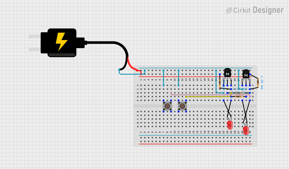
Explore Projects Built with 22mm Pushbutton
Technical Specifications
- Button Diameter: 22mm
- Rated Voltage: Typically 12V, 24V, or 220V AC/DC (varies by model)
- Rated Current: 3A to 10A (depending on the specific model)
- Contact Configuration: Normally Open (NO), Normally Closed (NC), or both
- Mounting Hole Diameter: 22mm
- Material: Plastic or metal housing with a durable actuator
- Ingress Protection (IP) Rating: IP65 or higher for dust and water resistance (varies by model)
- Operating Temperature: -25°C to 55°C (typical range)
Pin Configuration and Descriptions
The 22mm pushbutton typically has screw terminals or quick-connect terminals for wiring. Below is a general description of the pin configuration:
| Pin Label | Description |
|---|---|
| NO | Normally Open contact terminal |
| NC | Normally Closed contact terminal |
| COM | Common terminal for the switch |
Note: The exact pin configuration may vary depending on the manufacturer. Always refer to the datasheet for your specific model.
Usage Instructions
Mounting the Pushbutton:
- Drill a 22mm hole in the panel or enclosure where the pushbutton will be installed.
- Insert the pushbutton into the hole and secure it using the provided locking nut.
Wiring the Pushbutton:
- Identify the terminals (NO, NC, and COM) on the pushbutton.
- Connect the COM terminal to the power source or control circuit.
- For a Normally Open (NO) configuration, connect the load or control input to the NO terminal. The circuit will close when the button is pressed.
- For a Normally Closed (NC) configuration, connect the load or control input to the NC terminal. The circuit will open when the button is pressed.
Connecting to an Arduino UNO (Example):
- The 22mm pushbutton can be used as an input device for an Arduino UNO. Below is an example circuit and code:
- Connect the COM terminal to the ground (GND) pin on the Arduino.
- Connect the NO terminal to a digital input pin (e.g., pin 2) on the Arduino.
- Use a pull-up resistor (10kΩ) between the digital input pin and the 5V pin to ensure a stable signal.
- The 22mm pushbutton can be used as an input device for an Arduino UNO. Below is an example circuit and code:
// Example code for using a 22mm pushbutton with Arduino UNO
const int buttonPin = 2;  // Pin connected to the pushbutton
const int ledPin = 13;    // Pin connected to the onboard LED

int buttonState = 0;      // Variable to store the button state

void setup() {
  pinMode(buttonPin, INPUT);  // Set the button pin as input
  pinMode(ledPin, OUTPUT);    // Set the LED pin as output
  digitalWrite(ledPin, LOW);  // Ensure the LED is off initially
}

void loop() {
  buttonState = digitalRead(buttonPin);  // Read the state of the button

  if (buttonState == HIGH) {
    // If the button is pressed, turn on the LED
    digitalWrite(ledPin, HIGH);
  } else {
    // If the button is not pressed, turn off the LED
    digitalWrite(ledPin, LOW);
  }
}
- Important Considerations:
- Ensure the pushbutton's voltage and current ratings match your circuit requirements.
- For high-power applications, use the pushbutton to control a relay or contactor instead of directly switching the load.
- If the pushbutton is exposed to harsh environments, choose a model with a high IP rating for protection against dust and water.
Troubleshooting and FAQs
Common Issues
The pushbutton does not activate the circuit:
- Check the wiring to ensure the terminals are connected correctly.
- Verify that the pushbutton is not damaged or worn out.
- Ensure the power supply and load are functioning properly.
The circuit remains active even when the button is not pressed:
- Confirm that the correct terminal (NO or NC) is used for your application.
- Check for short circuits or incorrect wiring.
The pushbutton feels stuck or unresponsive:
- Inspect the button for physical damage or debris.
- Clean the button mechanism if necessary, following the manufacturer's guidelines.
FAQs
Q: Can I use a 22mm pushbutton for AC circuits?
A: Yes, as long as the pushbutton's voltage and current ratings are suitable for the AC circuit.
Q: How do I choose between NO and NC configurations?
A: Use NO for circuits that should activate when the button is pressed. Use NC for circuits that should deactivate when the button is pressed.
Q: Can I use the pushbutton outdoors?
A: Only if the pushbutton has an appropriate IP rating (e.g., IP65 or higher) for outdoor use.