How to Use Charge controller: Examples, Pinouts, and Specs
Introduction
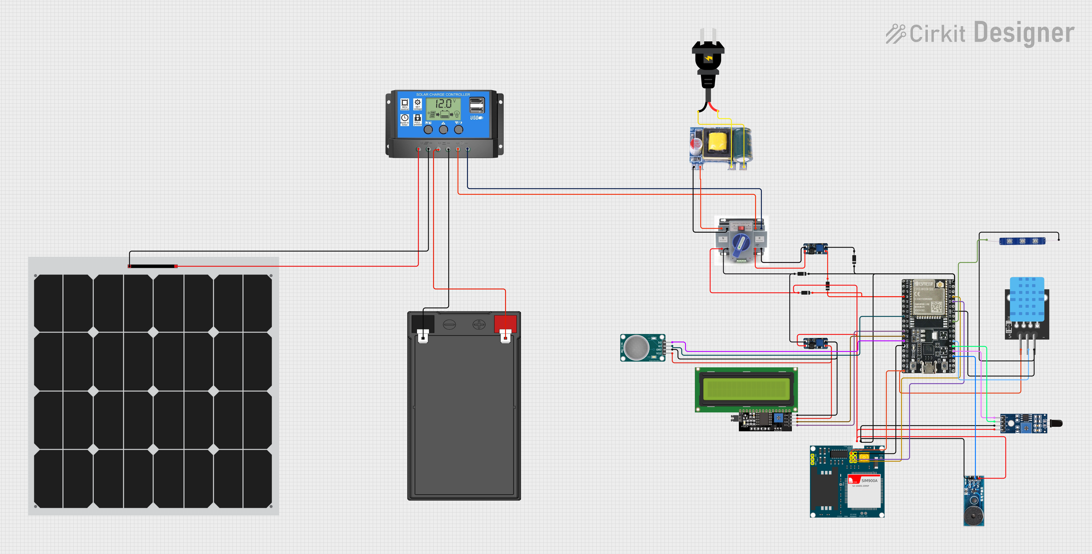
A charge controller, also known as a solar charge controller or solar regulator, is an essential component in solar power systems. It manages the power going into the battery bank from the solar array. It ensures that the deep cycle batteries are not overcharged during the day, and that the power doesn't run back to the solar panels overnight and drain the batteries. Fafeicy's charge controllers are designed to provide reliable battery management for off-grid renewable energy systems.
Explore Projects Built with Charge controller
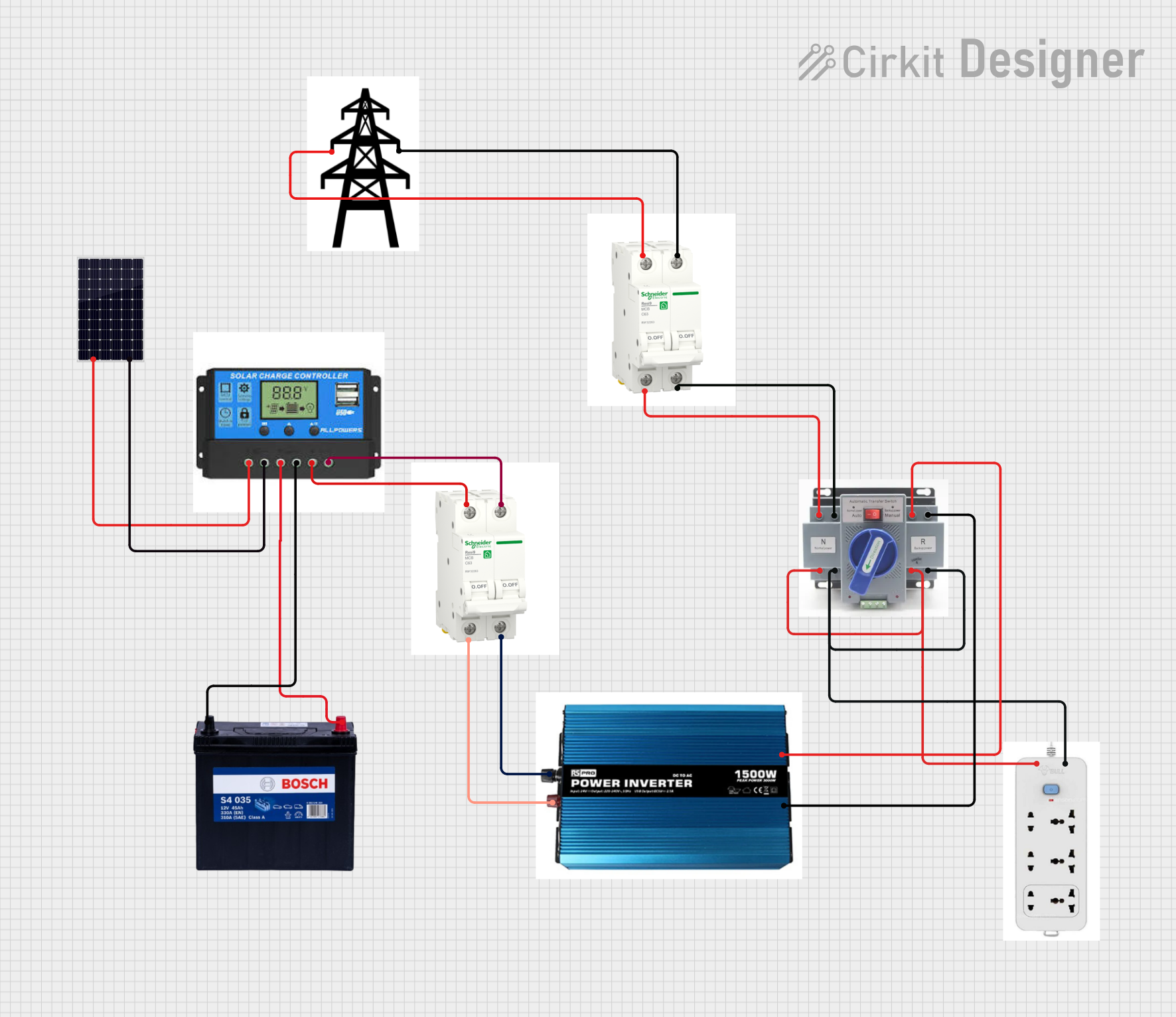
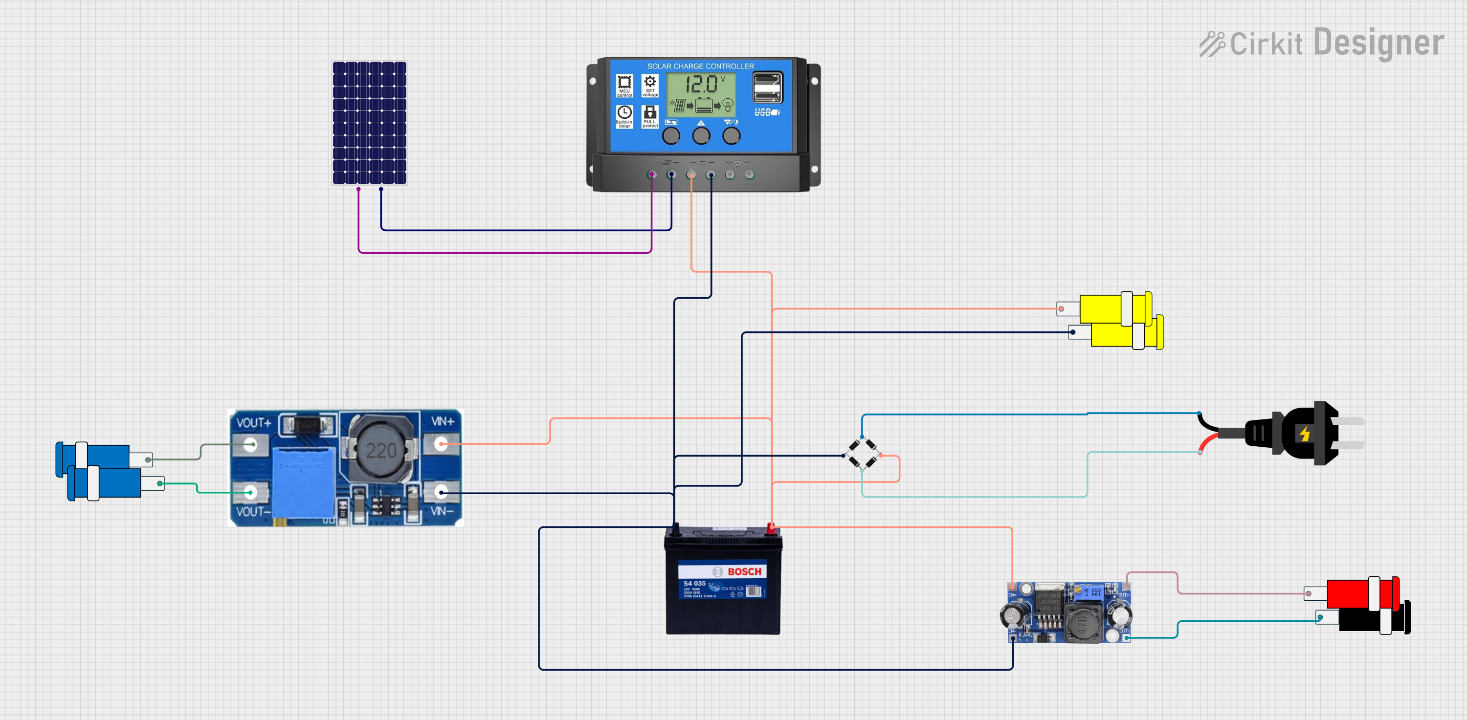
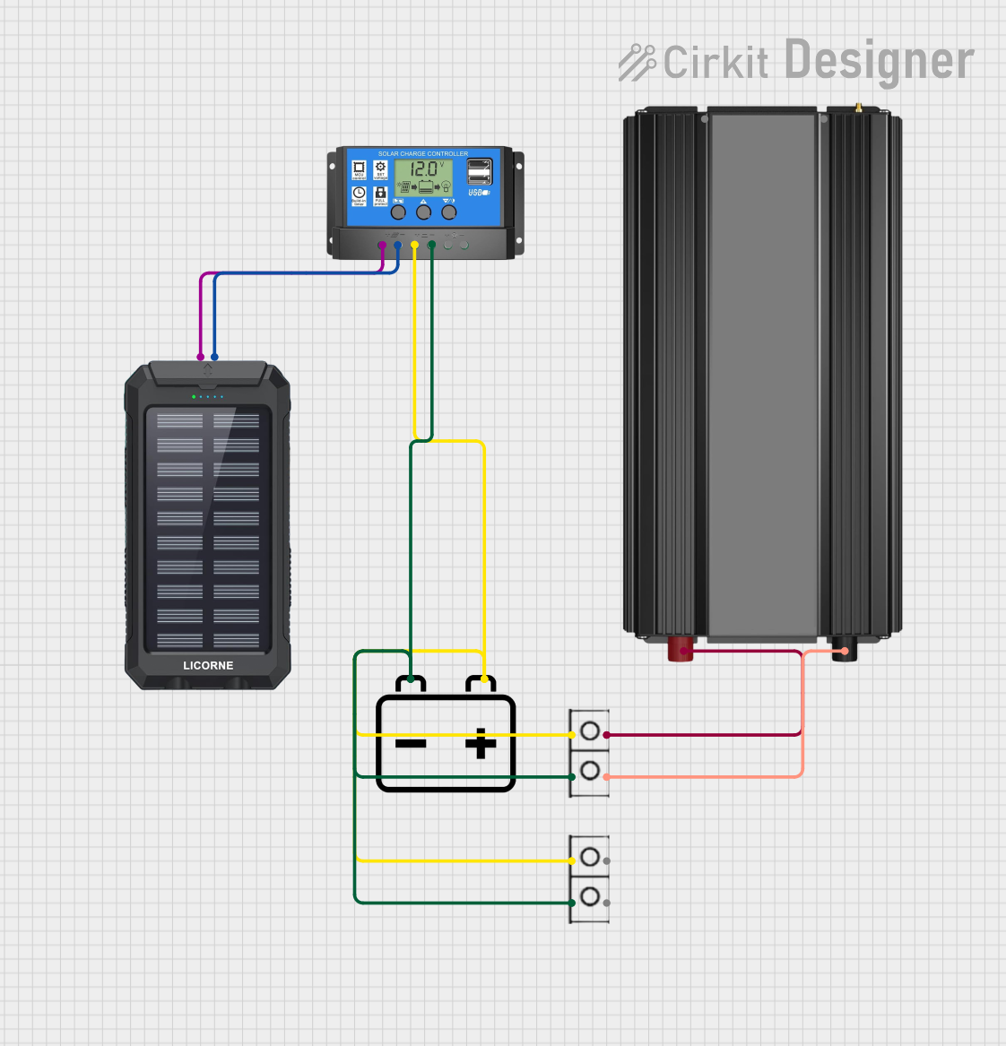
Explore Projects Built with Charge controller
Common Applications and Use Cases
- Solar power systems for homes, RVs, boats, and remote cabins
- Off-grid power systems for telecommunications and remote sensors
- Wind energy systems requiring battery charging
Technical Specifications
Key Technical Details
- Rated Voltage: 12V/24V Auto Adaptation
- Rated Current: 10A / 20A / 30A (depending on model)
- Max. PV Input Voltage: 50V
- Max. PV Input Power: 120W (12V), 240W (24V) for 10A model; proportionally higher for 20A and 30A models
- Self-Consumption: ≤10mA
- Charge Circuit Voltage Drop: ≤0.26V
- Discharge Circuit Voltage Drop: ≤0.15V
- Working Temperature: -35°C to +60°C
Pin Configuration and Descriptions
| Pin No. | Function | Description |
|---|---|---|
| 1 | Solar Panel (+) | Positive terminal for solar panel input |
| 2 | Solar Panel (-) | Negative terminal for solar panel input |
| 3 | Battery (+) | Positive terminal for battery connection |
| 4 | Battery (-) | Negative terminal for battery connection |
| 5 | Load (+) | Positive terminal for connecting the load (e.g., lights, TV) |
| 6 | Load (-) | Negative terminal for connecting the load |
Usage Instructions
How to Use the Component in a Circuit
Connecting the Battery:
- Ensure that the battery voltage matches the charge controller rating (12V/24V).
- Connect the battery's positive terminal to the charge controller's Battery (+) terminal.
- Connect the battery's negative terminal to the charge controller's Battery (-) terminal.
Connecting the Solar Panel:
- Verify that the solar panel's voltage and current do not exceed the charge controller's specifications.
- Connect the solar panel's positive terminal to the charge controller's Solar Panel (+) terminal.
- Connect the solar panel's negative terminal to the charge controller's Solar Panel (-) terminal.
Connecting the Load:
- Connect the load's positive terminal to the charge controller's Load (+) terminal.
- Connect the load's negative terminal to the charge controller's Load (-) terminal.
Important Considerations and Best Practices
- Always connect the battery first to ensure the charge controller recognizes the system voltage correctly.
- Use appropriate cable sizes to minimize voltage drop and ensure safety.
- Ensure the charge controller is mounted in a well-ventilated area to prevent overheating.
- Do not exceed the rated current of the charge controller by connecting loads or solar panels that are too powerful.
Troubleshooting and FAQs
Common Issues Users Might Face
Battery Not Charging:
- Check all connections for proper contact and correct polarity.
- Ensure the solar panel is receiving adequate sunlight.
- Verify that the solar panel voltage is within the acceptable range.
Load Not Working:
- Check the load connections and ensure the load does not exceed the controller's rated current.
- Verify that the battery has sufficient charge to power the load.
Solutions and Tips for Troubleshooting
- If the battery is not charging, measure the voltage at the solar panel terminals to ensure it falls within the required range.
- Ensure there is no shading on the solar panels, as this can significantly reduce their output.
- Regularly check the battery's state of charge and health to ensure it can hold a charge.
FAQs
Q: Can I connect a wind turbine to this charge controller? A: This charge controller is designed for solar panels. If you have a wind turbine, ensure it is compatible with the controller's specifications.
Q: What happens if the solar panel voltage exceeds the maximum input voltage? A: Exceeding the maximum PV input voltage can damage the charge controller. Always ensure the solar panel voltage is within the specified range.
Q: How do I know if the charge controller is working? A: Most charge controllers have LED indicators or a display that shows the charging status and battery voltage.
Q: Can I use this charge controller for a 24V battery system? A: Yes, this charge controller automatically adapts to 12V or 24V systems. Ensure your battery bank is configured correctly for the system voltage.
Please note that this documentation is a general guide and may not cover all aspects of the Fafeicy charge controller. For specific models, refer to the manufacturer's datasheet and manual for detailed instructions and safety information.