How to Use boost conventer: Examples, Pinouts, and Specs
Introduction
A boost converter is a DC-DC converter that steps up (increases) the input voltage to a higher output voltage while maintaining power balance. It is widely used in applications where the input voltage is lower than the required output voltage. The boost converter operates by storing energy in an inductor and releasing it at a higher voltage.
Explore Projects Built with boost conventer
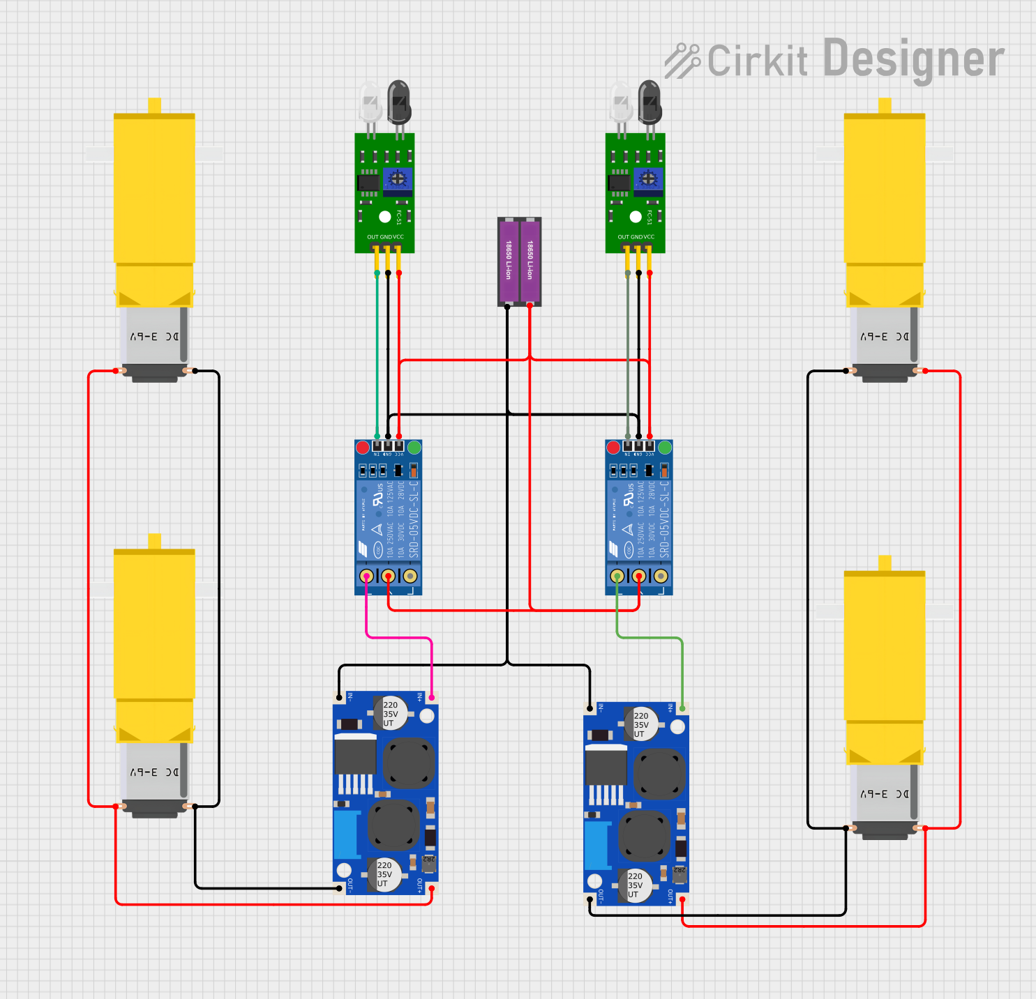

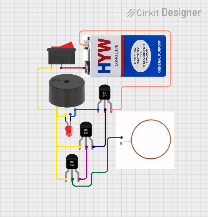

Explore Projects Built with boost conventer
Common Applications and Use Cases
- Battery-powered devices (e.g., stepping up voltage from a single-cell battery)
- Solar power systems
- LED drivers
- Electric vehicles
- Power supply units for microcontrollers and sensors
Technical Specifications
The technical specifications of a boost converter can vary depending on the specific model. Below are general specifications for a typical boost converter module:
| Parameter | Value |
|---|---|
| Input Voltage Range | 3V to 32V |
| Output Voltage Range | 5V to 35V |
| Maximum Output Current | 2A to 5A (depending on the model) |
| Efficiency | Up to 95% |
| Switching Frequency | 150 kHz |
| Operating Temperature | -40°C to +85°C |
Pin Configuration and Descriptions
Below is the pin configuration for a common boost converter module:
| Pin Name | Description |
|---|---|
| VIN | Input voltage pin. Connect the positive terminal of the input power source. |
| GND | Ground pin. Connect the negative terminal of the input power source. |
| VOUT | Output voltage pin. Provides the boosted voltage to the load. |
| EN (optional) | Enable pin. Used to turn the boost converter on or off (active high). |
Usage Instructions
How to Use the Boost Converter in a Circuit
Connect the Input Voltage:
- Connect the positive terminal of the input power source to the
VINpin. - Connect the negative terminal of the input power source to the
GNDpin.
- Connect the positive terminal of the input power source to the
Set the Output Voltage:
- Most boost converters have a potentiometer for adjusting the output voltage.
- Use a multimeter to measure the output voltage at the
VOUTpin while turning the potentiometer until the desired voltage is achieved.
Connect the Load:
- Connect the positive terminal of the load to the
VOUTpin. - Connect the negative terminal of the load to the
GNDpin.
- Connect the positive terminal of the load to the
Enable the Converter (if applicable):
- If the module has an
ENpin, ensure it is connected to a high logic level (e.g., 3.3V or 5V) to enable the converter.
- If the module has an
Important Considerations and Best Practices
- Input Voltage Range: Ensure the input voltage is within the specified range of the boost converter.
- Output Voltage Adjustment: Do not exceed the maximum output voltage rating of the module.
- Current Limit: Ensure the load does not draw more current than the maximum output current rating.
- Heat Dissipation: Use a heatsink or active cooling if the module gets too hot during operation.
- Capacitor Placement: Place input and output capacitors close to the module to reduce voltage ripple.
Example: Using a Boost Converter with Arduino UNO
Below is an example of using a boost converter to power an Arduino UNO with a 9V output:
- Connect a 5V power source (e.g., a USB power bank) to the
VINandGNDpins of the boost converter. - Adjust the potentiometer to set the output voltage to 9V.
- Connect the
VOUTpin of the boost converter to theVINpin of the Arduino UNO. - Connect the
GNDpin of the boost converter to theGNDpin of the Arduino UNO.
Here is a simple Arduino code to blink an LED while powered by the boost converter:
// Simple LED Blink Code for Arduino UNO
// Ensure the boost converter is providing 9V to the Arduino's VIN pin.

const int ledPin = 13; // Built-in LED pin on Arduino UNO

void setup() {
  pinMode(ledPin, OUTPUT); // Set the LED pin as an output
}

void loop() {
  digitalWrite(ledPin, HIGH); // Turn the LED on
  delay(1000);                // Wait for 1 second
  digitalWrite(ledPin, LOW);  // Turn the LED off
  delay(1000);                // Wait for 1 second
}
Troubleshooting and FAQs
Common Issues and Solutions
No Output Voltage:
- Check the input voltage and ensure it is within the specified range.
- Verify that the
ENpin is connected to a high logic level (if applicable). - Inspect the connections for loose wires or poor solder joints.
Output Voltage is Incorrect:
- Adjust the potentiometer to set the correct output voltage.
- Ensure the load is not drawing more current than the module's maximum rating.
Module Overheating:
- Reduce the load current or improve heat dissipation with a heatsink or fan.
- Check for short circuits in the wiring.
High Voltage Ripple:
- Add additional input and output capacitors to reduce voltage ripple.
- Ensure the capacitors are placed close to the module.
FAQs
Q: Can I use a boost converter to power a microcontroller directly?
A: Yes, but ensure the output voltage is within the operating range of the microcontroller. For example, an Arduino UNO can be powered via its VIN pin with a voltage between 7V and 12V.
Q: What happens if the input voltage exceeds the specified range?
A: Exceeding the input voltage range can damage the boost converter. Always use a power source within the recommended range.
Q: Can I use a boost converter to charge a battery?
A: Yes, but you must ensure the output voltage and current are suitable for the battery type. Additionally, use a proper charging circuit to prevent overcharging.
Q: Why is the output voltage unstable?
A: This could be due to insufficient input power, excessive load current, or poor capacitor placement. Check the power source and connections.
By following this documentation, you can effectively use a boost converter in your electronic projects.