How to Use a7670E LTE Module: Examples, Pinouts, and Specs
Introduction
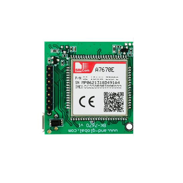
The a7670E LTE Module is a compact and versatile cellular communication module manufactured by Arduino (Part ID: 8712367816376). It is designed to enable high-speed data transmission over LTE networks, making it an excellent choice for Internet of Things (IoT) applications. This module supports multiple frequency bands, ensuring reliable connectivity in diverse environments, including remote locations.
Explore Projects Built with a7670E LTE Module


Explore Projects Built with a7670E LTE Module
Common Applications and Use Cases
- IoT devices requiring cellular connectivity
- Remote monitoring and control systems
- Smart agriculture and environmental monitoring
- Asset tracking and fleet management
- Industrial automation and telemetry
- Smart home and building automation
Technical Specifications
Key Technical Details
| Parameter | Specification |
|---|---|
| Manufacturer | Arduino |
| Part ID | 8712367816376 |
| Network Support | LTE Cat-1, GSM/GPRS/EDGE |
| Frequency Bands | LTE: B1/B3/B5/B7/B8/B20/B28 |
| Data Rate (LTE) | Uplink: 5 Mbps, Downlink: 10 Mbps |
| Operating Voltage | 3.3V to 4.2V |
| Power Consumption | Idle: ~5mA, Active: ~300mA |
| Operating Temperature | -40°C to +85°C |
| Communication Interface | UART, USB, GPIO |
| Dimensions | 30mm x 30mm x 3mm |
Pin Configuration and Descriptions
The a7670E LTE Module has a total of 10 pins. Below is the pinout and description:
| Pin Number | Pin Name | Description |
|---|---|---|
| 1 | VCC | Power supply input (3.3V to 4.2V) |
| 2 | GND | Ground |
| 3 | TXD | UART Transmit Data (connect to RX of host MCU) |
| 4 | RXD | UART Receive Data (connect to TX of host MCU) |
| 5 | USB_D+ | USB Data Positive (for USB communication) |
| 6 | USB_D- | USB Data Negative (for USB communication) |
| 7 | GPIO1 | General Purpose Input/Output 1 |
| 8 | GPIO2 | General Purpose Input/Output 2 |
| 9 | RESET | Reset pin (active low) |
| 10 | ANT | Antenna connection for LTE signal |
Usage Instructions
How to Use the a7670E LTE Module in a Circuit
- Power Supply: Connect the VCC pin to a regulated 3.3V to 4.2V power source and GND to the ground of your circuit.
- UART Communication: Connect the TXD and RXD pins to the corresponding RX and TX pins of your microcontroller (e.g., Arduino UNO).
- Antenna: Attach an LTE-compatible antenna to the ANT pin for optimal signal reception.
- USB Communication (Optional): If USB communication is required, connect USB_D+ and USB_D- to the USB interface of your host device.
- Reset: Use the RESET pin to restart the module if needed. Pull it low momentarily to trigger a reset.
Important Considerations and Best Practices
- Ensure the power supply is stable and within the specified voltage range to avoid damage to the module.
- Use a high-quality LTE antenna to maximize signal strength and data transmission reliability.
- Place the module away from high-frequency noise sources to minimize interference.
- For UART communication, configure the baud rate to 115200 bps (default) or as required by your application.
- Use proper ESD protection when handling the module to prevent damage from static electricity.
Example: Connecting the a7670E LTE Module to an Arduino UNO
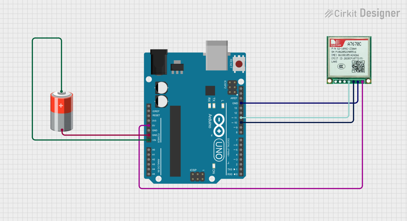
Below is an example of how to connect and use the a7670E LTE Module with an Arduino UNO:
Wiring Diagram
| a7670E Pin | Arduino UNO Pin |
|---|---|
| VCC | 3.3V |
| GND | GND |
| TXD | D2 (RX) |
| RXD | D3 (TX) |
| RESET | D4 |
Arduino Code Example
#include <SoftwareSerial.h>

// Define software serial pins for communication with the a7670E module
SoftwareSerial lteModule(2, 3); // RX = Pin 2, TX = Pin 3

void setup() {
  // Initialize serial communication with the module and the Serial Monitor
  Serial.begin(9600); // Communication with Serial Monitor
  lteModule.begin(115200); // Communication with a7670E module

  Serial.println("Initializing a7670E LTE Module...");
  delay(1000);

  // Send an AT command to check communication
  lteModule.println("AT");
}

void loop() {
  // Check for data from the module
  if (lteModule.available()) {
    String response = lteModule.readString();
    Serial.println("Module Response: " + response);
  }

  // Check for user input from the Serial Monitor
  if (Serial.available()) {
    String command = Serial.readString();
    lteModule.println(command); // Send command to the module
  }
}
Notes:
- Ensure the
SoftwareSeriallibrary is installed in your Arduino IDE. - Use the Serial Monitor to send AT commands (e.g.,
AT+CSQto check signal quality).
Troubleshooting and FAQs
Common Issues and Solutions
Module Not Responding to AT Commands
- Ensure the module is powered correctly and the connections are secure.
- Verify the baud rate is set to 115200 bps in your code.
- Check if the RESET pin is accidentally held low.
Poor Signal Strength
- Ensure the antenna is securely connected to the ANT pin.
- Move the module to an area with better LTE network coverage.
- Use a higher-gain antenna if necessary.
High Power Consumption
- Check for short circuits or incorrect wiring.
- Ensure the power supply can handle the module's peak current (~300mA).
USB Communication Not Working
- Verify the USB_D+ and USB_D- connections.
- Ensure the correct drivers are installed on your host device.
FAQs
Q1: Can the a7670E LTE Module work with 5V logic levels?
A1: No, the module operates at 3.3V logic levels. Use a level shifter if interfacing with a 5V microcontroller.
Q2: What is the default baud rate of the module?
A2: The default baud rate is 115200 bps.
Q3: Does the module support SMS functionality?
A3: Yes, the module supports SMS sending and receiving using AT commands.
Q4: Can I use the module without an external antenna?
A4: No, an external antenna is required for proper LTE signal reception.
Q5: Is the module compatible with 2G networks?
A5: Yes, the module supports GSM/GPRS/EDGE for 2G connectivity.