How to Use FC F405 V4: Examples, Pinouts, and Specs
Introduction
The FC F405 V4 by SpeedyBee is a high-performance flight controller designed specifically for multirotor drones. It features advanced processing capabilities, multiple input/output ports, and compatibility with a wide range of sensors and peripherals. This flight controller is ideal for both hobbyists and professionals, offering robust support for various flight modes and configurations. Its compact design and versatile functionality make it a popular choice for building and upgrading drones.
Explore Projects Built with FC F405 V4


Explore Projects Built with FC F405 V4
Common Applications and Use Cases
- Multirotor drones (quadcopters, hexacopters, octocopters)
- FPV (First-Person View) racing drones
- Aerial photography and videography platforms
- Autonomous drone projects
- Educational and research applications in robotics and UAVs
Technical Specifications
Key Technical Details
- Processor: STM32F405 (32-bit ARM Cortex-M4 core with FPU)
- IMU (Inertial Measurement Unit): MPU6000 (6-axis gyro and accelerometer)
- Input Voltage Range: 3S–6S LiPo (9V–30V)
- BEC Output: 5V @ 2A, 9V @ 2A
- UART Ports: 5 UARTs for peripherals (e.g., GPS, telemetry, receivers)
- ESC Signal Output: 8 PWM outputs
- OSD: Integrated Betaflight OSD (On-Screen Display)
- Flash Memory: 16MB for Blackbox logging
- Barometer: BMP280
- Dimensions: 36mm x 36mm (30.5mm x 30.5mm mounting holes)
- Weight: 7.5g
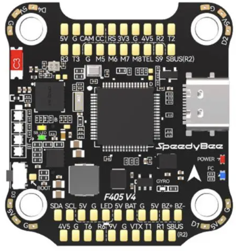
Pin Configuration and Descriptions
The FC F405 V4 features a well-labeled pinout for easy connection to peripherals. Below is a summary of the key pins:
| Pin Name | Description |
|---|---|
| GND | Ground connection for power and peripherals |
| VBAT | Battery voltage input (9V–30V) |
| 5V | 5V output for powering peripherals (e.g., receiver, GPS) |
| 9V | 9V output for powering FPV equipment (e.g., VTX, camera) |
| RX1, TX1 | UART1 for telemetry or receiver connection |
| RX2, TX2 | UART2 for GPS or other peripherals |
| RX3, TX3 | UART3 for additional peripherals |
| RX4, TX4 | UART4 for additional peripherals |
| RX5, TX5 | UART5 for additional peripherals |
| M1–M8 | Motor signal outputs (PWM) for ESCs |
| LED | Addressable LED strip signal output |
| Buzzer | Buzzer signal output for audible alerts |
| I2C_SCL, I2C_SDA | I2C interface for external sensors (e.g., magnetometer, barometer) |
| RSSI | Analog RSSI input for receiver signal strength monitoring |
| CAM | Camera signal input for FPV systems |
| VTX | Video transmitter signal output for FPV systems |
Usage Instructions
How to Use the FC F405 V4 in a Circuit
Powering the Flight Controller:
- Connect the battery's positive terminal to the VBAT pin and the negative terminal to GND.
- Ensure the input voltage is within the supported range (9V–30V).
Connecting Motors and ESCs:
- Connect the signal wires from the ESCs to the M1–M8 pins.
- Ensure the ESCs are properly calibrated and configured for the desired motor layout.
Connecting Peripherals:
- Use the UART ports (RX/TX) to connect peripherals such as GPS, telemetry modules, or receivers.
- Connect FPV components (camera and VTX) to the CAM and VTX pins, respectively.
Configuring the Flight Controller:
- Install Betaflight Configurator on your computer.
- Connect the flight controller to your computer via USB.
- Use Betaflight Configurator to flash firmware, configure settings, and calibrate sensors.
Mounting the Flight Controller:
- Secure the flight controller to the drone frame using the 30.5mm x 30.5mm mounting holes.
- Use vibration-dampening materials to minimize interference with the IMU.
Important Considerations and Best Practices
- Power Supply: Ensure the power supply is stable and within the specified voltage range to avoid damage.
- Orientation: Verify the flight controller's orientation matches the configuration in Betaflight.
- Firmware Updates: Regularly update the firmware to access new features and improvements.
- Blackbox Logging: Use the onboard 16MB flash memory for flight data logging and analysis.
- Heat Management: Avoid overheating by ensuring proper airflow around the flight controller.
Example Code for Arduino UNO Integration
While the FC F405 V4 is not typically used with an Arduino UNO, you can use an Arduino to send commands or read telemetry data via UART. Below is an example of how to communicate with the flight controller using an Arduino:
#include <SoftwareSerial.h>

// Define RX and TX pins for SoftwareSerial
SoftwareSerial mySerial(10, 11); // RX = pin 10, TX = pin 11

void setup() {
  // Initialize serial communication
  Serial.begin(9600); // For debugging with the PC
  mySerial.begin(115200); // Communication with FC F405 V4

  Serial.println("Arduino is ready to communicate with FC F405 V4.");
}

void loop() {
  // Send a test command to the flight controller
  mySerial.println("Test Command");

  // Check if data is available from the flight controller
  if (mySerial.available()) {
    String data = mySerial.readString();
    Serial.println("Data from FC F405 V4: " + data);
  }

  delay(1000); // Wait 1 second before sending the next command
}
Troubleshooting and FAQs
Common Issues and Solutions
Flight Controller Not Powering On:
- Verify the battery is connected properly and the voltage is within the supported range.
- Check for loose or damaged connections on the power input pins.
Motors Not Spinning:
- Ensure the ESCs are connected to the correct motor output pins (M1–M8).
- Verify motor configuration and calibration in Betaflight.
No Communication with Betaflight Configurator:
- Check the USB cable for data transfer capability (some cables are charge-only).
- Ensure the correct COM port is selected in Betaflight Configurator.
Unstable Flight or Drifting:
- Calibrate the accelerometer and gyro in Betaflight.
- Check for vibrations affecting the IMU and use vibration-dampening materials.
No Video Signal in FPV System:
- Verify the camera and VTX are connected to the correct pins (CAM and VTX).
- Ensure the VTX is powered and configured to the correct channel.
FAQs
Can I use the FC F405 V4 with 2S LiPo batteries?
- No, the minimum supported input voltage is 9V (3S LiPo).
Does the flight controller support GPS?
- Yes, GPS modules can be connected via UART ports.
What firmware is compatible with the FC F405 V4?
- The flight controller is compatible with Betaflight firmware.
Can I use this flight controller for fixed-wing aircraft?
- While designed for multirotors, it can be configured for fixed-wing use in Betaflight.
How do I reset the flight controller to factory settings?
- Use the "Reset Settings" option in Betaflight Configurator or flash the firmware again.
This concludes the documentation for the FC F405 V4 by SpeedyBee. For further assistance, refer to the official user manual or contact SpeedyBee support.