How to Use Led 5mm Red: Examples, Pinouts, and Specs
Introduction
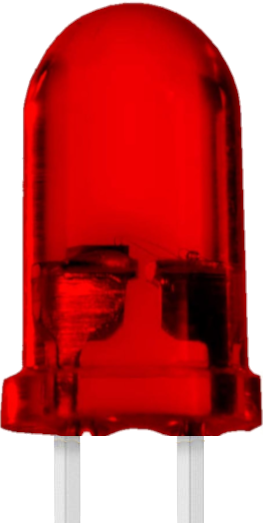
A 5mm red light-emitting diode (LED) is a compact and efficient electronic component that emits red light when an electric current flows through it. It is widely used in various applications due to its low power consumption, long lifespan, and reliability. Commonly, this LED is used as an indicator in electronic devices, status displays, and decorative lighting.
Explore Projects Built with Led 5mm Red

Explore Projects Built with Led 5mm Red
Technical Specifications
The following are the key technical details of the 5mm red LED:
| Parameter | Value |
|---|---|
| Forward Voltage (Vf) | 1.8V to 2.2V |
| Forward Current (If) | 20mA (typical), 30mA (maximum) |
| Reverse Voltage (Vr) | 5V (maximum) |
| Wavelength | 620nm to 630nm (red light) |
| Viewing Angle | 20° to 30° |
| Power Dissipation | 60mW (maximum) |
| Operating Temperature | -40°C to +85°C |
| Package Size | 5mm (diameter) |
Pin Configuration and Descriptions
The 5mm red LED has two pins:
| Pin Name | Description |
|---|---|
| Anode (+) | The longer leg of the LED. Connect this to the positive terminal of the circuit. |
| Cathode (-) | The shorter leg of the LED. Connect this to the negative terminal or ground. |
Usage Instructions
How to Use the Component in a Circuit
Determine the Resistor Value: To prevent damage to the LED, a current-limiting resistor must be used. The resistor value can be calculated using Ohm's Law: [ R = \frac{V_{supply} - V_f}{I_f} ]
- (V_{supply}): Supply voltage
- (V_f): Forward voltage of the LED (1.8V to 2.2V)
- (I_f): Desired forward current (typically 20mA or 0.02A)
For example, if (V_{supply} = 5V) and (V_f = 2V): [ R = \frac{5V - 2V}{0.02A} = 150\Omega ]
Connect the LED:
- Connect the anode (+) to the positive terminal of the power supply through the resistor.
- Connect the cathode (-) to the ground.
Power the Circuit: Apply the appropriate voltage to the circuit. The LED will emit red light.
Important Considerations and Best Practices
- Polarity Matters: Ensure the anode and cathode are connected correctly. Reversing the polarity may damage the LED.
- Use a Resistor: Always use a current-limiting resistor to avoid exceeding the maximum forward current.
- Avoid Overheating: Do not exceed the maximum power dissipation or operating temperature range.
- Series or Parallel Connections: When using multiple LEDs, calculate the resistor values for each configuration.
Example: Connecting to an Arduino UNO
The 5mm red LED can be easily interfaced with an Arduino UNO. Below is an example circuit and code:
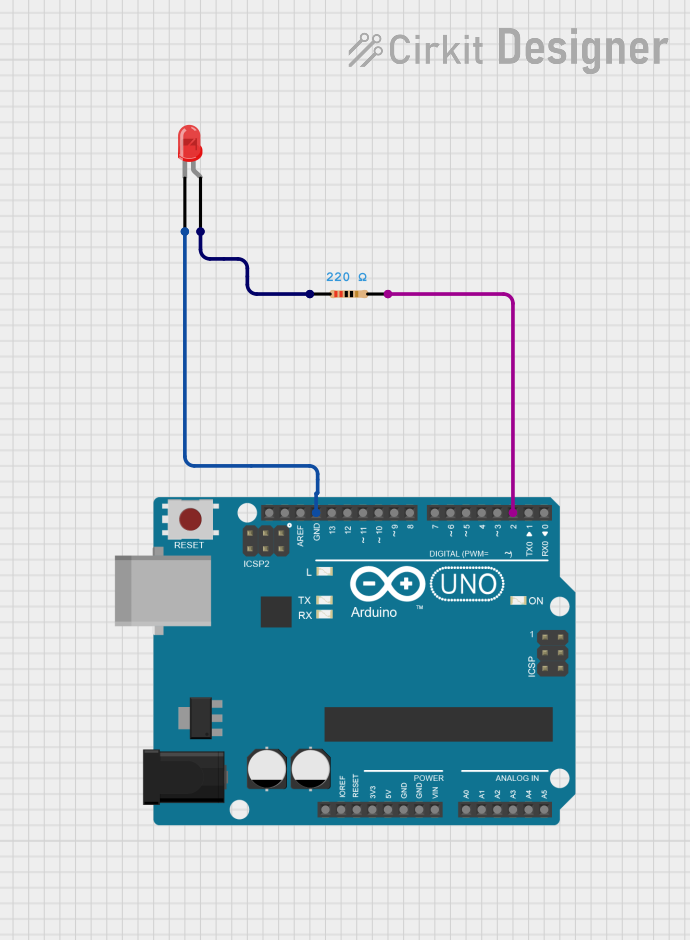
Circuit Setup
- Connect the anode (+) of the LED to a 220Ω resistor.
- Connect the other end of the resistor to digital pin 13 on the Arduino.
- Connect the cathode (-) of the LED to the Arduino's GND pin.
Arduino Code
// Example code to blink a 5mm red LED connected to pin 13 of Arduino UNO

// Define the pin where the LED is connected
const int ledPin = 13;

void setup() {
  // Set the LED pin as an output
  pinMode(ledPin, OUTPUT);
}

void loop() {
  // Turn the LED on
  digitalWrite(ledPin, HIGH);
  delay(1000); // Wait for 1 second

  // Turn the LED off
  digitalWrite(ledPin, LOW);
  delay(1000); // Wait for 1 second
}
Troubleshooting and FAQs
Common Issues and Solutions
LED Does Not Light Up:
Cause: Incorrect polarity.
Solution: Ensure the anode is connected to the positive terminal and the cathode to ground.
Cause: No current-limiting resistor or incorrect resistor value.
Solution: Use a resistor with the correct value as calculated above.
LED is Dim:
- Cause: Insufficient current.
- Solution: Check the resistor value and ensure the supply voltage is adequate.
LED Burns Out Quickly:
- Cause: Excessive current or voltage.
- Solution: Verify the resistor value and ensure the supply voltage does not exceed the LED's ratings.
Flickering LED:
- Cause: Unstable power supply or loose connections.
- Solution: Check the power source and ensure all connections are secure.
FAQs
Q: Can I connect the LED directly to a 5V power supply?
A: No, you must use a current-limiting resistor to prevent damage to the LED.Q: What happens if I reverse the polarity of the LED?
A: The LED will not light up, and prolonged reverse voltage may damage it.Q: Can I use the LED with a 3.3V power supply?
A: Yes, but you still need to calculate and use an appropriate resistor to limit the current.Q: How do I connect multiple LEDs in a circuit?
A: You can connect LEDs in series or parallel, but ensure each configuration has the correct resistor values to limit current.
This documentation provides all the essential details to use a 5mm red LED effectively in your projects.