How to Use Arduino UNO+WiFi R3 ATmega328P+Node MCU ESP8266 CH340G: Examples, Pinouts, and Specs
Introduction
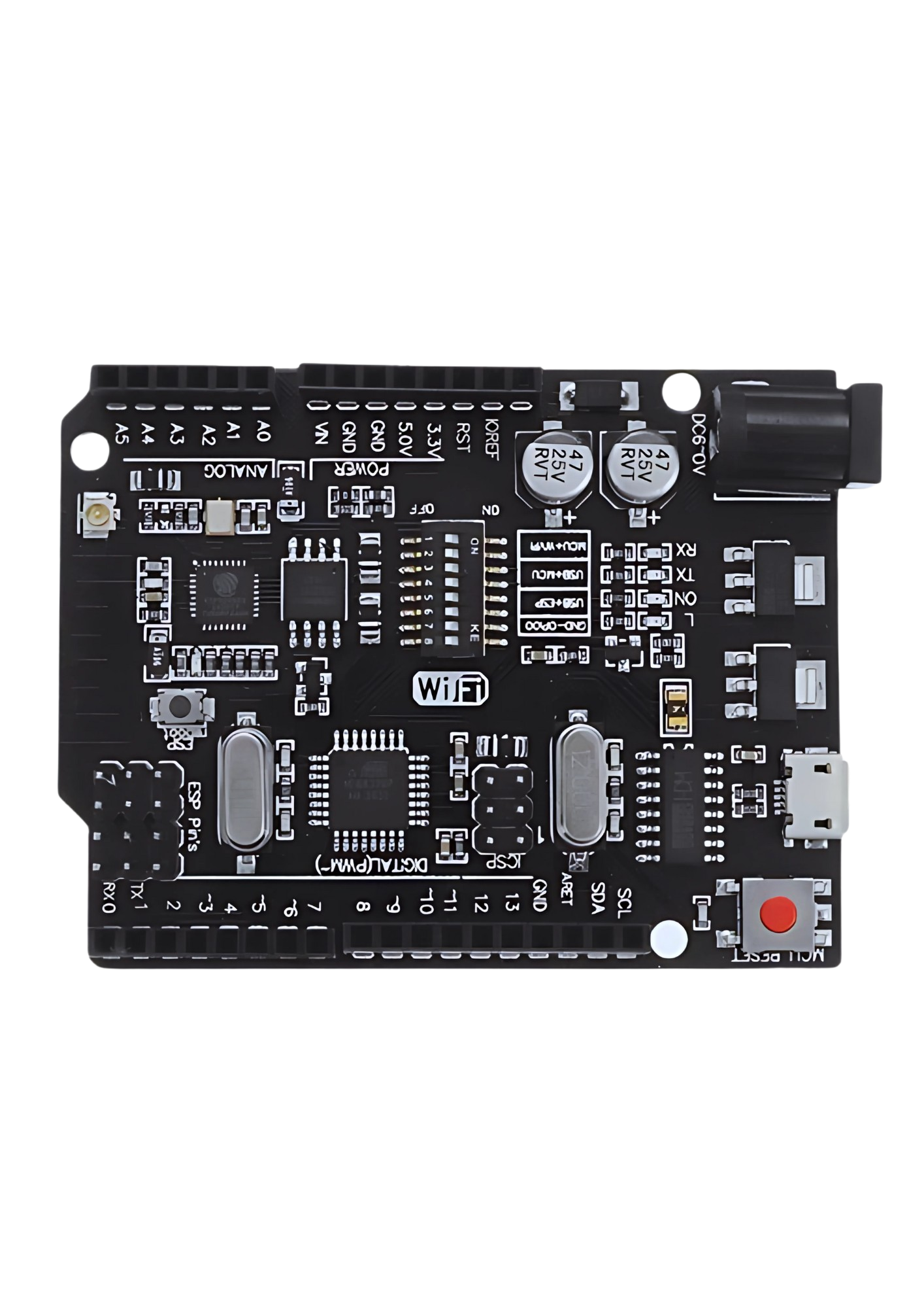
The Arduino UNO+WiFi R3 ATmega328P+ESP8266 (CH340G) is a microcontroller board developed by Robocraze that integrates the features of an Arduino UNO with the WiFi capabilities of the ESP8266 module. This board is designed for hobbyists, educators, and professionals who require both the traditional Arduino interface and wireless connectivity in their projects. It is ideal for applications such as smart home devices, IoT projects, and wireless sensor networks.
Explore Projects Built with Arduino UNO+WiFi R3 ATmega328P+Node MCU ESP8266 CH340G
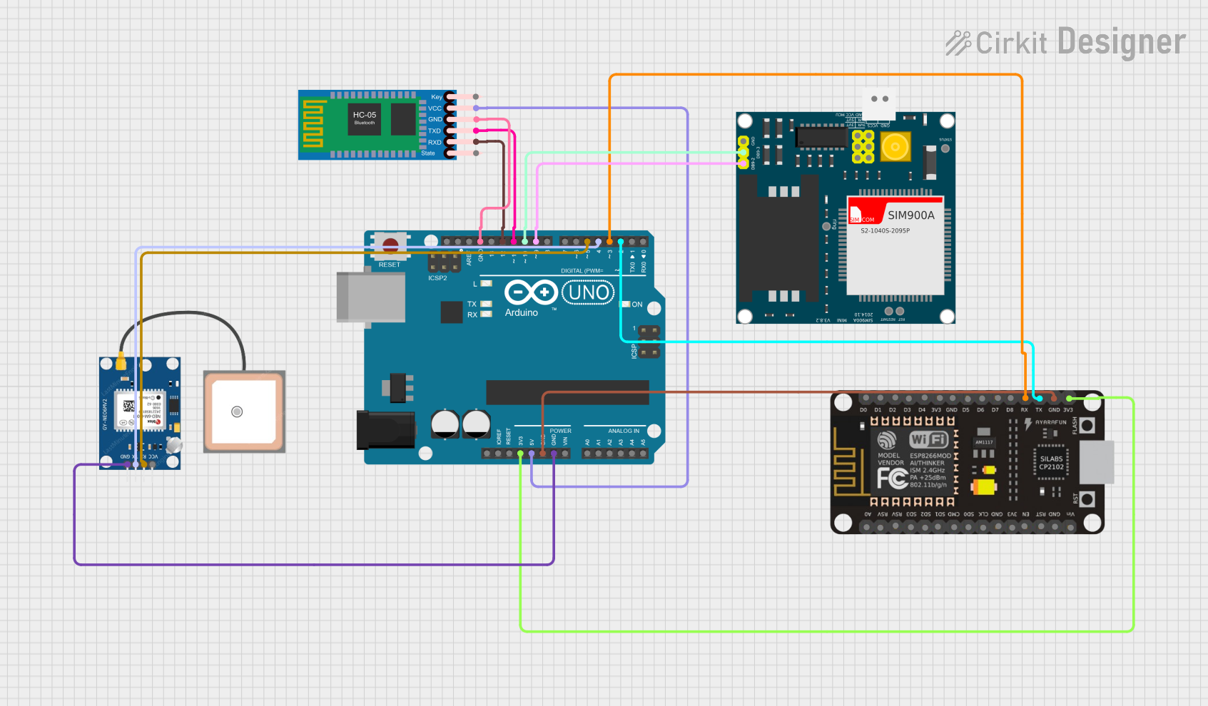
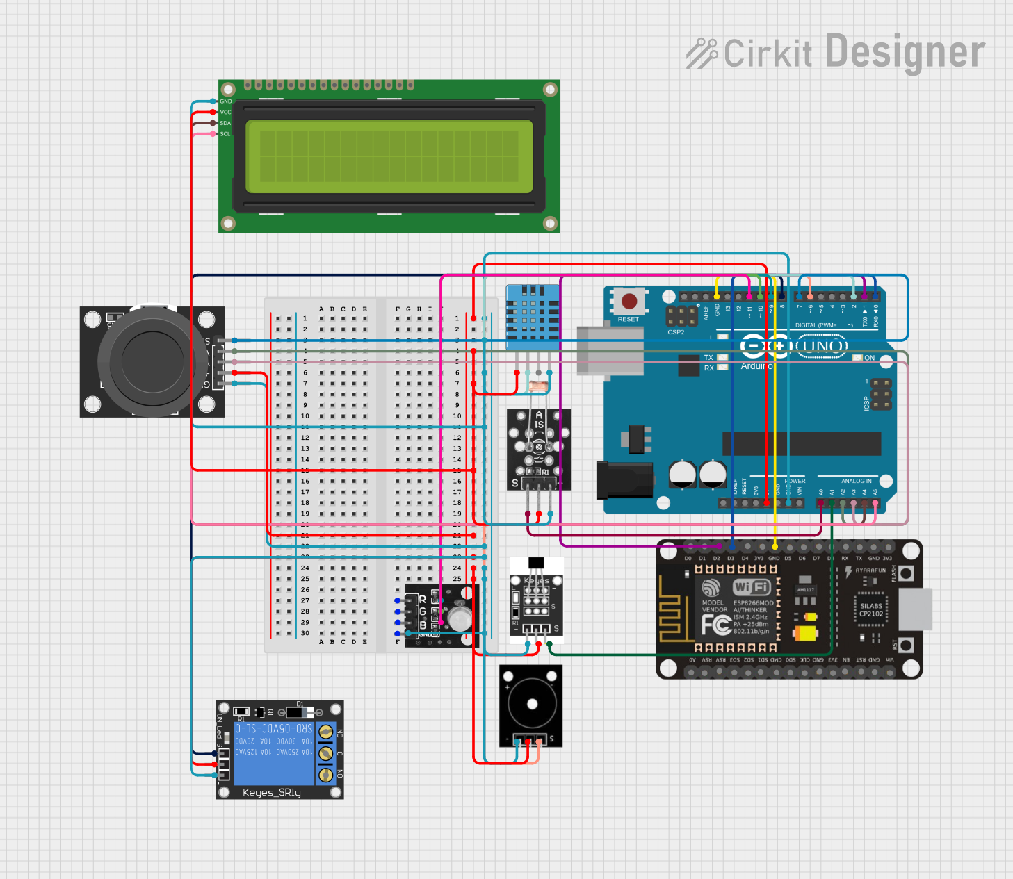
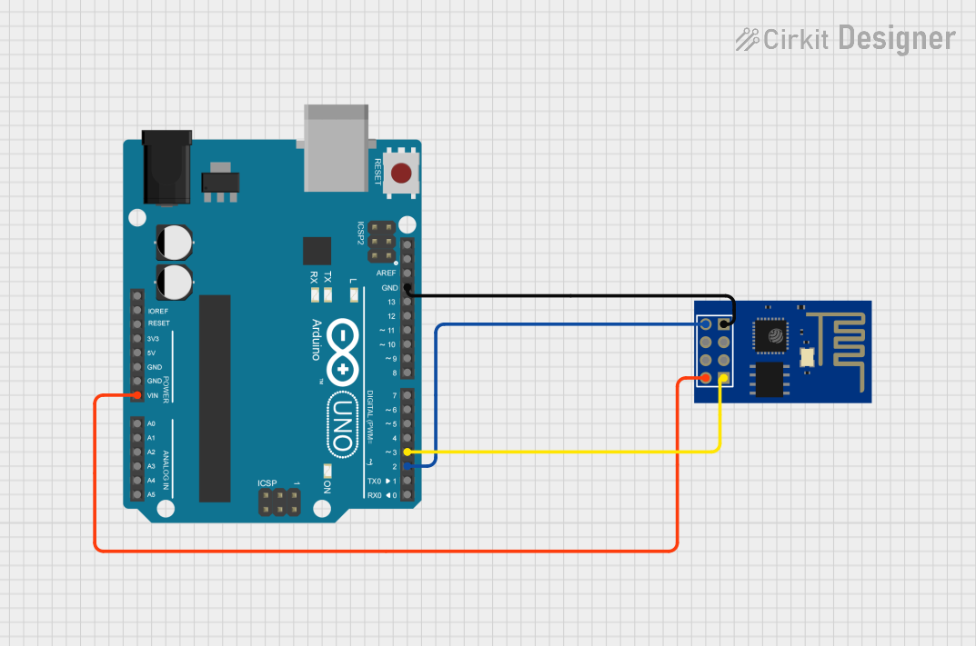
Explore Projects Built with Arduino UNO+WiFi R3 ATmega328P+Node MCU ESP8266 CH340G
Technical Specifications
General Features
- Microcontroller: ATmega328P
- WiFi Module: ESP8266
- USB-to-Serial Converter: CH340G
- Input Voltage (recommended): 7-12V
- Input Voltage (limit): 6-20V
- Digital I/O Pins: 14 (of which 6 provide PWM output)
- Analog Input Pins: 6
- DC Current per I/O Pin: 20 mA
- DC Current for 3.3V Pin: 50 mA
- Flash Memory: 32 KB (ATmega328P) of which 0.5 KB used by bootloader
- SRAM: 2 KB (ATmega328P)
- EEPROM: 1 KB (ATmega328P)
- Clock Speed: 16 MHz
- Wi-Fi Standard: 802.11 b/g/n
- Frequency: 2.4 GHz
Pin Configuration
| Pin Number | Function | Description |
|---|---|---|
| 1 | TXD | Transmit Data (Serial Output) |
| 2 | RXD | Receive Data (Serial Input) |
| 3-8 | Digital I/O | Digital Input/Output Pins |
| 9-14 | PWM/Digital I/O | PWM Output Capable Digital Pins |
| A0-A5 | Analog Input | Analog Input Pins |
| A6-A7 | Analog Input | Analog Input Pins (SMD Package Only) |
| VIN | Voltage Input | Input Voltage for the Board |
| 5V | 5V Output | Regulated 5V Output |
| 3.3V | 3.3V Output | Regulated 3.3V Output |
| GND | Ground | Ground Pins |
| RST | Reset | Reset Pin |
Usage Instructions
Setting Up the Board
- Connect the Arduino UNO+WiFi board to your computer using a USB cable.
- Ensure that you have the latest version of the Arduino IDE installed.
- Open the Arduino IDE, go to Tools > Board, and select "Arduino/Genuino UNO".
- Select the appropriate COM port under Tools > Port.
Programming the ATmega328P
- Write your Arduino sketch in the IDE.
- Click the "Upload" button to program the ATmega328P microcontroller.
Programming the ESP8266
- To program the ESP8266, you must switch the onboard toggle to the ESP position.
- Select the appropriate board (e.g., "Generic ESP8266 Module") in the Arduino IDE.
- Choose the correct settings for the ESP8266 module (CPU frequency, flash size, etc.).
- Write your sketch and upload it in the same manner as the ATmega328P.
Connecting to WiFi
#include <ESP8266WiFi.h>

// Replace with your network credentials
const char* ssid = "your_SSID";
const char* password = "your_PASSWORD";

void setup() {
  Serial.begin(115200); // Start serial communication at 115200 baud
  WiFi.begin(ssid, password); // Connect to the WiFi network

  while (WiFi.status() != WL_CONNECTED) { // Wait for connection
    delay(500);
    Serial.print(".");
  }
  Serial.println("");
  Serial.print("Connected to ");
  Serial.println(ssid);
  Serial.print("IP address: ");
  Serial.println(WiFi.localIP());
}

void loop() {
  // Your code here
}
Best Practices
- Always disconnect the board from power sources before making or altering connections.
- Use a proper power supply to prevent damage to the board.
- Avoid exposing the board to static electricity or physical shocks.
- When programming the ESP8266, ensure that the ATmega328P is not trying to use the same serial ports.
Troubleshooting and FAQs
Common Issues
- Board not recognized by the computer: Ensure that the CH340G drivers are installed.
- Cannot upload to the ESP8266: Check that the board is in ESP mode and the correct settings are selected in the IDE.
- WiFi connection issues: Verify that the SSID and password are correct and that the WiFi network is within range.
FAQs
Q: Can I use the Arduino UNO+WiFi board as a regular Arduino UNO? A: Yes, the board can be used as a regular Arduino UNO when the onboard switch is set to the ATmega328P position.
Q: How do I reset the ESP8266 module? A: You can reset the ESP8266 by briefly connecting the RST pin to GND.
Q: Can I use the ESP8266 and ATmega328P at the same time? A: Yes, but you need to ensure they are not using the same serial ports for communication.
For further assistance, consult the Robocraze community forums or contact technical support.