Cirkit Designer Logo
Cirkit Designer
Your all-in-one circuit design IDE
Home / 
Component Documentation

How to Use voltage sensor: Examples, Pinouts, and Specs

Image of voltage sensor
Cirkit Designer LogoDesign with voltage sensor in Cirkit Designer

Introduction

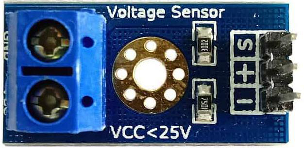
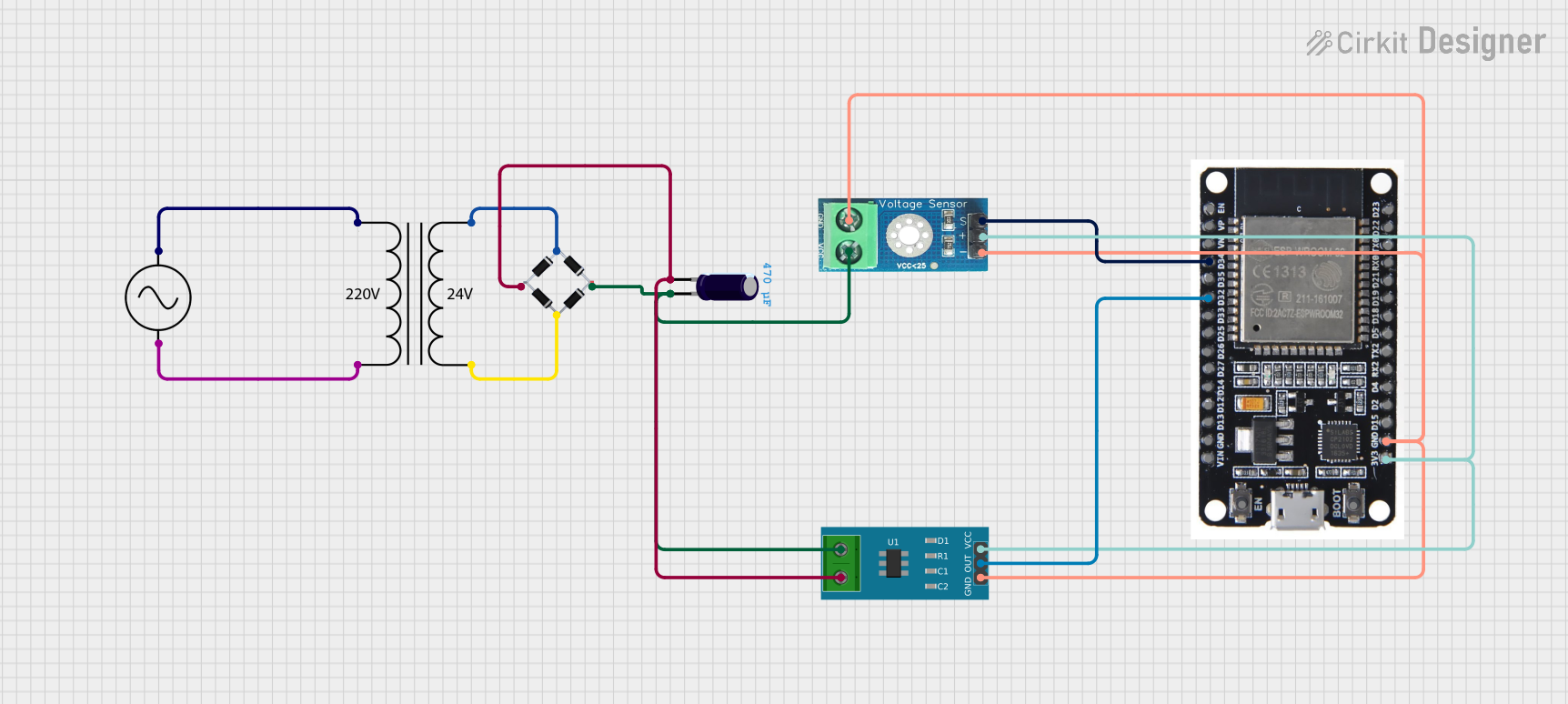
A voltage sensor is a device that detects and measures the voltage level in a circuit, providing feedback for monitoring and control purposes. Manufactured by 2wef with the part ID 123454225435632y, this voltage sensor is designed for accurate and reliable voltage measurement in a variety of applications.

Explore Projects Built with voltage sensor

Use Cirkit Designer to design, explore, and prototype these projects online. Some projects support real-time simulation. Click "Open Project" to start designing instantly!
Arduino UNO-Based Voltage Monitoring System with SMS Alerts via SIM800L
Image of GSM800 Voltage  sensor: A project utilizing voltage sensor in a practical application
This circuit is designed to monitor voltage levels from two 240V power sources using a pair of voltage sensors connected to an Arduino UNO. The Arduino reads the sensor outputs and, if a voltage higher than 10V is detected, it uses a SIM800L GSM module to send an SMS alert. The system is powered by a Polymer Lithium Ion Battery, and resistors are used for voltage level shifting for the SIM800L communication with the Arduino.
Cirkit Designer LogoOpen Project in Cirkit Designer
Arduino Mega 2560 and Adafruit DS1841 Battery-Powered Sensor Interface
Image of Capacitance meter: A project utilizing voltage sensor in a practical application
This circuit is a sensor interface system powered by a 9V battery, featuring an Arduino Mega 2560 microcontroller and an Adafruit DS1841 digital potentiometer. The circuit includes resistors and capacitors for signal conditioning, with the Arduino handling data acquisition and communication via I2C with the DS1841.
Cirkit Designer LogoOpen Project in Cirkit Designer
Arduino UNO and ZMPT101B-Based AC Voltage Monitor with I2C LCD Display
Image of mmm: A project utilizing voltage sensor in a practical application
This circuit is designed to monitor AC voltage using a ZMPT101B voltage sensor and display the readings on a 16x2 I2C LCD. An Arduino UNO processes the sensor data, and if the voltage exceeds predefined thresholds, it activates a buzzer to alert the user.
Cirkit Designer LogoOpen Project in Cirkit Designer
ESP32-Based Voltage and Current Monitoring System with Wi-Fi Connectivity
Image of Sustainability: A project utilizing voltage sensor in a practical application
This circuit is designed to measure and monitor voltage and current using an ESP32 microcontroller. It includes a voltage sensor and a current sensor connected to the ESP32, which reads the sensor data and outputs the measurements to the Serial Monitor. The circuit also features a power supply system with an AC source, a transformer, and a bridge rectifier to provide the necessary DC voltage for the sensors and microcontroller.
Cirkit Designer LogoOpen Project in Cirkit Designer

Explore Projects Built with voltage sensor

Use Cirkit Designer to design, explore, and prototype these projects online. Some projects support real-time simulation. Click "Open Project" to start designing instantly!
Image of GSM800 Voltage  sensor: A project utilizing voltage sensor in a practical application
Arduino UNO-Based Voltage Monitoring System with SMS Alerts via SIM800L
This circuit is designed to monitor voltage levels from two 240V power sources using a pair of voltage sensors connected to an Arduino UNO. The Arduino reads the sensor outputs and, if a voltage higher than 10V is detected, it uses a SIM800L GSM module to send an SMS alert. The system is powered by a Polymer Lithium Ion Battery, and resistors are used for voltage level shifting for the SIM800L communication with the Arduino.
Cirkit Designer LogoOpen Project in Cirkit Designer
Image of Capacitance meter: A project utilizing voltage sensor in a practical application
Arduino Mega 2560 and Adafruit DS1841 Battery-Powered Sensor Interface
This circuit is a sensor interface system powered by a 9V battery, featuring an Arduino Mega 2560 microcontroller and an Adafruit DS1841 digital potentiometer. The circuit includes resistors and capacitors for signal conditioning, with the Arduino handling data acquisition and communication via I2C with the DS1841.
Cirkit Designer LogoOpen Project in Cirkit Designer
Image of mmm: A project utilizing voltage sensor in a practical application
Arduino UNO and ZMPT101B-Based AC Voltage Monitor with I2C LCD Display
This circuit is designed to monitor AC voltage using a ZMPT101B voltage sensor and display the readings on a 16x2 I2C LCD. An Arduino UNO processes the sensor data, and if the voltage exceeds predefined thresholds, it activates a buzzer to alert the user.
Cirkit Designer LogoOpen Project in Cirkit Designer
Image of Sustainability: A project utilizing voltage sensor in a practical application
ESP32-Based Voltage and Current Monitoring System with Wi-Fi Connectivity
This circuit is designed to measure and monitor voltage and current using an ESP32 microcontroller. It includes a voltage sensor and a current sensor connected to the ESP32, which reads the sensor data and outputs the measurements to the Serial Monitor. The circuit also features a power supply system with an AC source, a transformer, and a bridge rectifier to provide the necessary DC voltage for the sensors and microcontroller.
Cirkit Designer LogoOpen Project in Cirkit Designer

Common Applications and Use Cases

  • Battery monitoring systems
  • Power supply regulation
  • Renewable energy systems (e.g., solar panels)
  • Industrial automation and control
  • Educational projects and prototyping with microcontrollers (e.g., Arduino)

Technical Specifications

The voltage sensor is designed to measure DC voltages and provide a scaled-down analog output for interfacing with microcontrollers or other devices.

Key Technical Details

  • Input Voltage Range: 0–25V DC
  • Output Voltage Range: 0–5V DC (scaled for microcontroller ADC input)
  • Accuracy: ±1% (typical)
  • Operating Voltage: 3.3V or 5V DC
  • Current Consumption: <10mA
  • Operating Temperature: -40°C to 85°C
  • Dimensions: 30mm x 20mm x 10mm

Pin Configuration and Descriptions

The voltage sensor typically has a 3-pin interface for easy connection to a microcontroller or other devices. The pinout is as follows:

Pin Number Pin Name Description
1 VCC Power supply input (3.3V or 5V DC)
2 GND Ground connection
3 OUT Analog voltage output (0–5V DC)

Usage Instructions

How to Use the Voltage Sensor in a Circuit

  1. Power the Sensor: Connect the VCC pin to a 3.3V or 5V DC power source and the GND pin to the ground of your circuit.
  2. Connect the Output: Attach the OUT pin to the analog input pin of your microcontroller (e.g., Arduino).
  3. Voltage Measurement: The sensor outputs a scaled-down voltage proportional to the input voltage. For example, if the input voltage is 25V, the output voltage will be 5V.

Important Considerations and Best Practices

  • Voltage Divider: The sensor uses an internal voltage divider to scale down the input voltage. Ensure the input voltage does not exceed the sensor's maximum rating (25V DC).
  • Calibration: For precise measurements, calibrate the sensor by comparing its output with a known reference voltage.
  • Noise Reduction: Use decoupling capacitors near the sensor to minimize noise in the output signal.
  • Microcontroller Compatibility: Ensure the microcontroller's ADC reference voltage matches the sensor's output range (e.g., 5V for Arduino UNO).

Example Code for Arduino UNO

Below is an example code snippet to read the voltage sensor's output using an Arduino UNO:

// Define the analog pin connected to the sensor's OUT pin
const int sensorPin = A0;

// Define the maximum input voltage of the sensor (25V in this case)
const float maxInputVoltage = 25.0;

// Define the maximum output voltage of the sensor (5V)
const float maxOutputVoltage = 5.0;

void setup() {
  Serial.begin(9600); // Initialize serial communication at 9600 baud
}

void loop() {
  // Read the analog value from the sensor
  int sensorValue = analogRead(sensorPin);

  // Convert the analog value to a voltage (0-5V range)
  float outputVoltage = (sensorValue / 1023.0) * maxOutputVoltage;

  // Scale the output voltage to the input voltage range (0-25V)
  float inputVoltage = (outputVoltage / maxOutputVoltage) * maxInputVoltage;

  // Print the measured input voltage to the Serial Monitor
  Serial.print("Input Voltage: ");
  Serial.print(inputVoltage);
  Serial.println(" V");

  delay(1000); // Wait for 1 second before the next reading
}

Troubleshooting and FAQs

Common Issues and Solutions

  1. No Output Voltage:

    • Cause: Incorrect wiring or no power supply.
    • Solution: Verify all connections and ensure the sensor is powered correctly.
  2. Inaccurate Voltage Readings:

    • Cause: Lack of calibration or noise in the circuit.
    • Solution: Calibrate the sensor using a reference voltage and add decoupling capacitors.
  3. Microcontroller Not Detecting Output:

    • Cause: Incorrect analog pin configuration or damaged sensor.
    • Solution: Check the microcontroller's pin configuration and test the sensor with a multimeter.

FAQs

  • Q: Can this sensor measure AC voltage?

    • A: No, this sensor is designed for DC voltage measurement only.
  • Q: What happens if the input voltage exceeds 25V?

    • A: Exceeding the maximum input voltage may damage the sensor. Use a higher-rated voltage divider if needed.
  • Q: Is this sensor compatible with 3.3V microcontrollers?

    • A: Yes, the sensor works with both 3.3V and 5V systems, but ensure the output voltage does not exceed the ADC reference voltage of your microcontroller.

This documentation provides all the necessary details to effectively use the 2wef 123454225435632y Voltage Sensor in your projects.