How to Use UPS (5V, 1A): Examples, Pinouts, and Specs
Introduction
The UPS (5V, 1A) is a compact and reliable Uninterruptible Power Supply designed to provide a stable 5V output with a maximum current of 1A. It ensures continuous power delivery to connected devices during power outages or voltage fluctuations, making it ideal for critical applications where uninterrupted operation is essential. This component is commonly used in IoT devices, microcontroller-based systems, and portable electronics to prevent data loss or system crashes caused by power interruptions.
Explore Projects Built with UPS (5V, 1A)


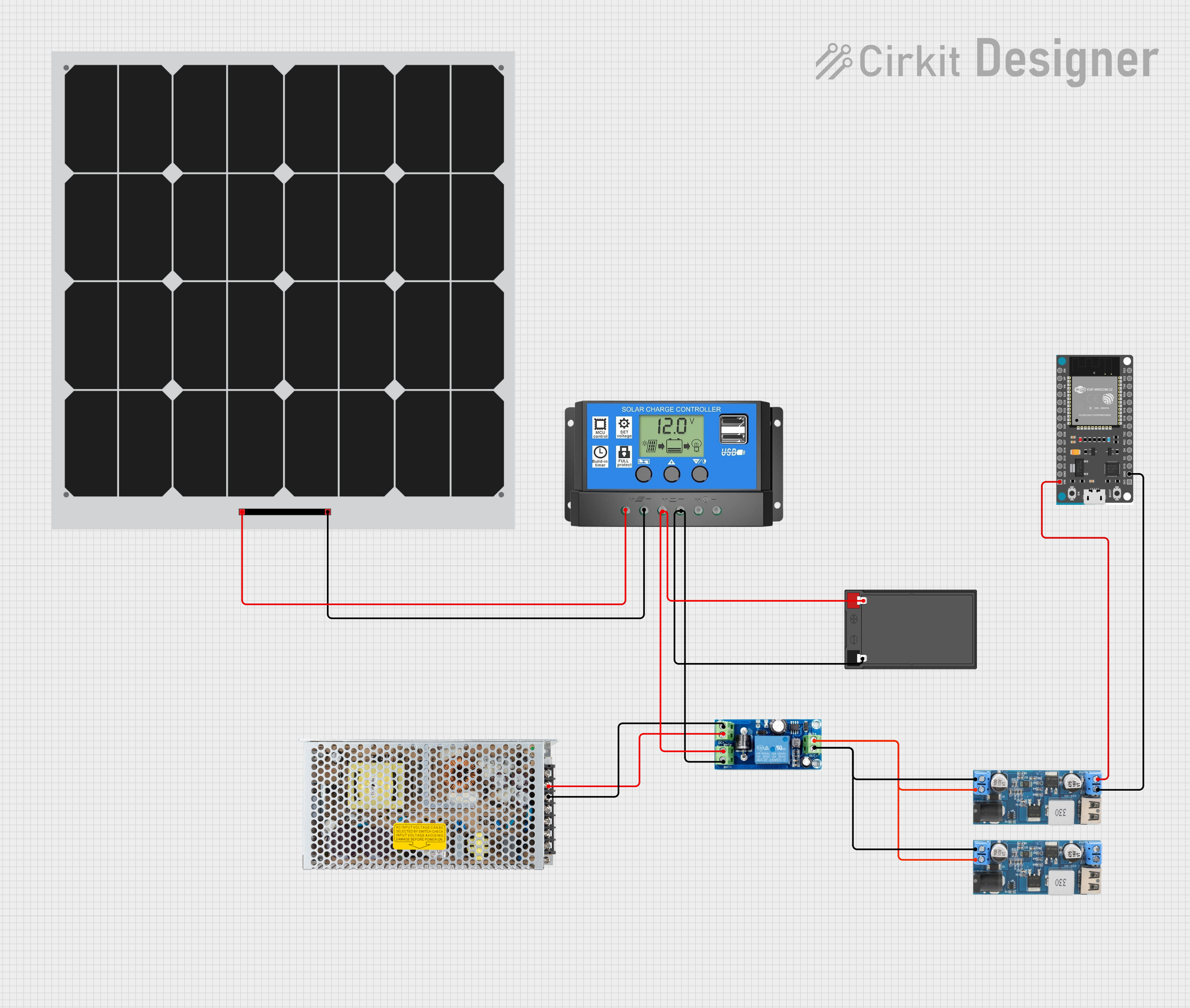

Explore Projects Built with UPS (5V, 1A)
Common Applications and Use Cases
- Power backup for Raspberry Pi, Arduino, and other microcontroller boards.
- IoT devices requiring uninterrupted operation.
- Portable electronics and battery-powered systems.
- Network equipment such as routers and modems.
- Emergency lighting and small-scale security systems.
Technical Specifications
The following table outlines the key technical details of the UPS (5V, 1A):
| Parameter | Value |
|---|---|
| Input Voltage Range | 5V DC ± 5% |
| Output Voltage | 5V DC |
| Maximum Output Current | 1A |
| Battery Type | Lithium-ion (3.7V, 18650) |
| Charging Current | 500mA |
| Backup Time | Depends on battery capacity |
| Efficiency | ≥ 85% |
| Protection Features | Overcharge, Overdischarge, |
| Short Circuit, Overcurrent |
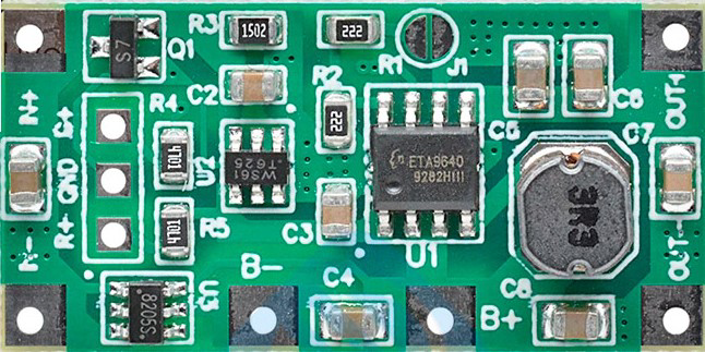
Pin Configuration and Descriptions
The UPS module typically has the following pins and connectors:
| Pin/Connector | Description |
|---|---|
| VIN | Input voltage pin (5V DC). Connect to a 5V power source for charging the battery. |
| VOUT | Output voltage pin (5V DC). Provides stable power to the connected load. |
| GND | Ground pin. Common ground for input, output, and battery. |
| BAT+ | Positive terminal for the lithium-ion battery. |
| BAT- | Negative terminal for the lithium-ion battery. |
Usage Instructions
How to Use the Component in a Circuit
Connect the Input Power Source:
- Connect a 5V DC power source to the
VINpin andGNDpin. This will charge the internal battery and power the load simultaneously.
- Connect a 5V DC power source to the
Connect the Load:
- Attach the device or circuit requiring uninterrupted power to the
VOUTpin andGNDpin. Ensure the load does not exceed the 1A current limit.
- Attach the device or circuit requiring uninterrupted power to the
Connect the Battery:
- Attach a 3.7V lithium-ion battery to the
BAT+andBAT-terminals. Ensure correct polarity to avoid damage.
- Attach a 3.7V lithium-ion battery to the
Verify Connections:
- Double-check all connections before powering the circuit to prevent short circuits or incorrect wiring.
Important Considerations and Best Practices
- Battery Selection: Use a high-quality 3.7V lithium-ion battery with sufficient capacity to meet your backup time requirements.
- Load Current: Ensure the connected load does not exceed the 1A maximum output current to avoid overloading the UPS.
- Heat Dissipation: If the UPS operates under high load for extended periods, ensure proper ventilation to prevent overheating.
- Testing: Periodically test the UPS by disconnecting the input power source to verify that the battery backup functions correctly.
Example: Using the UPS with an Arduino UNO
The UPS can be used to power an Arduino UNO during power outages. Below is an example circuit and code:
Circuit Connections
- Connect the
VOUTpin of the UPS to the5Vpin of the Arduino UNO. - Connect the
GNDpin of the UPS to theGNDpin of the Arduino UNO. - Connect a 5V DC power source to the
VINpin of the UPS.
Example Code
// Example code to demonstrate uninterrupted operation of an Arduino UNO
// powered by the UPS (5V, 1A) during power outages.

void setup() {
  // Initialize serial communication for debugging
  Serial.begin(9600);
  Serial.println("Arduino is powered by the UPS!");
}

void loop() {
  // Simulate a task that runs continuously
  Serial.println("Running uninterrupted...");
  delay(1000); // Wait for 1 second
}
Troubleshooting and FAQs
Common Issues and Solutions
No Output Voltage
- Cause: The battery is not connected or is discharged.
- Solution: Ensure the battery is properly connected and charged. Verify the input power source is supplying 5V.
UPS Overheating
- Cause: The load exceeds the 1A current limit or poor ventilation.
- Solution: Reduce the load current and ensure proper airflow around the UPS.
Battery Not Charging
- Cause: Faulty battery or incorrect wiring.
- Solution: Check the battery connections and replace the battery if necessary.
Frequent Power Interruptions
- Cause: Insufficient battery capacity or degraded battery.
- Solution: Use a higher-capacity battery or replace the battery if it is old.
FAQs
Q1: Can I use a different battery type with the UPS?
A1: No, the UPS is designed specifically for 3.7V lithium-ion batteries. Using a different battery type may damage the module.
Q2: How long will the UPS provide backup power?
A2: The backup time depends on the battery capacity and the load current. For example, a 2000mAh battery can power a 500mA load for approximately 4 hours.
Q3: Can I use the UPS without a battery?
A3: Yes, the UPS can function as a power regulator without a battery, but it will not provide backup power during outages.
Q4: Is the UPS safe to use with sensitive electronics?
A4: Yes, the UPS includes protection features such as overcharge, overdischarge, and short-circuit protection, making it safe for sensitive devices.