How to Use 74HC75: Examples, Pinouts, and Specs

Introduction
The 74HC75 is a versatile digital logic component that functions as a quad 2-input multiplexer/demultiplexer. It is designed to select between two data inputs and route them to any of its four outputs. This component is widely used in digital circuits for data routing, signal selection, and various control applications where multiple data sources need to be managed efficiently.
Explore Projects Built with 74HC75


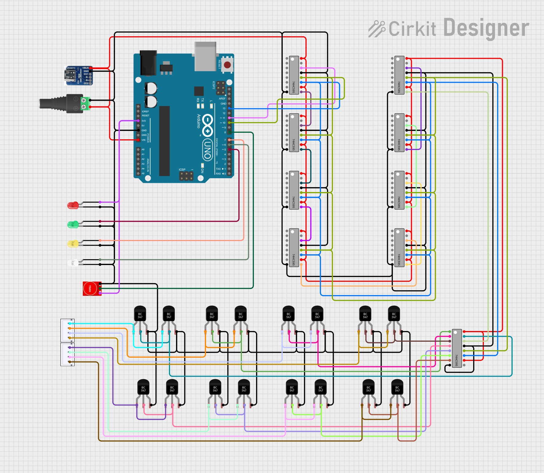
Explore Projects Built with 74HC75
Common Applications and Use Cases
- Data routing in digital communication systems
- Signal selection in multiplexing applications
- Control signal management in microcontroller-based projects
- Function as a switch in logic circuits
Technical Specifications
Key Technical Details
- Supply Voltage (Vcc): 2.0V to 6.0V
- High-Level Input Voltage (VIH): Minimum 2.0V
- Low-Level Input Voltage (VIL): Maximum 0.8V
- High-Level Output Voltage (VOH): Minimum 4.6V (when Vcc = 6.0V)
- Low-Level Output Voltage (VOL): Maximum 0.2V (when Vcc = 6.0V)
- Input Transition Rise/Fall Rate (V/ns): 0 to 1000 (Vcc = 2.0V to 6.0V)
- Operating Temperature Range: -40°C to +125°C
Pin Configuration and Descriptions
| Pin Number | Name | Description |
|---|---|---|
| 1 | S0 | Select input for multiplexer/demultiplexer |
| 2 | Z0 | Output/Input 0 |
| 3 | Z1 | Output/Input 1 |
| 4 | GND | Ground (0V) |
| 5 | Z2 | Output/Input 2 |
| 6 | Z3 | Output/Input 3 |
| 7 | E | Enable input (active LOW) |
| 8 | Vcc | Positive supply voltage |
| 9 | Y1 | Data input/output 1 |
| 10 | Y0 | Data input/output 0 |
| 11 | S1 | Select input for multiplexer/demultiplexer |
| 12-15 | Z4-Z7 | Output/Input 4-7 (for additional multiplexer sections) |
Usage Instructions
How to Use the 74HC75 in a Circuit
- Power Supply Connection: Connect Vcc to a positive supply voltage within the specified range and GND to the ground of the circuit.
- Enable the Device: Connect the E pin to ground (LOW) to enable the device. If the E pin is left unconnected or set to HIGH, the outputs will be in a high-impedance state.
- Select Input: Apply a logic level to the S0 and S1 pins to select the desired data input (Y0 or Y1) for routing to the outputs (Z0 to Z7).
- Data Inputs/Outputs: Connect the data inputs (Y0 and Y1) to the signals you wish to route. The selected input will be available at the outputs (Z0 to Z7) when the device is enabled.
Important Considerations and Best Practices
- Ensure that the supply voltage does not exceed the maximum rating to prevent damage to the device.
- Inputs should be driven by a high-impedance source or connected to a defined logic level to avoid floating inputs.
- Unused inputs should be tied to either Vcc or GND to ensure predictable operation.
- Decoupling capacitors (typically 0.1 µF) should be placed close to the Vcc pin to filter out noise.
Troubleshooting and FAQs
Common Issues
- Outputs Not Switching: Ensure that the E pin is connected to GND and that the S0 and S1 pins are receiving the correct logic levels.
- Unexpected Output States: Check that all unused inputs are tied to a known logic level to prevent floating inputs.
Solutions and Tips for Troubleshooting
- Verify that the supply voltage is within the specified range and that the ground connection is secure.
- Check the logic levels on the select and enable pins to ensure they are within the specified VIH and VIL ranges.
- Use an oscilloscope or logic analyzer to monitor the signals at the inputs and outputs to diagnose signal integrity issues.
FAQs
Q: Can the 74HC75 be used with an Arduino? A: Yes, the 74HC75 can be interfaced with an Arduino, provided that the logic levels are compatible.
Q: What happens if the enable pin is left floating? A: If the enable pin is left floating, the outputs may enter a high-impedance state, leading to unpredictable behavior.
Q: Can the 74HC75 be used as a demultiplexer? A: Yes, by using the outputs (Z0 to Z7) as select lines and the inputs (Y0 and Y1) as common data lines, the 74HC75 can function as a demultiplexer.
Example Arduino Code
Below is an example of how to control the 74HC75 with an Arduino UNO:
// Define the Arduino pin numbers for the 74HC75 control pins
const int enablePin = 2; // Connect to the E pin of 74HC75
const int selectPin0 = 3; // Connect to the S0 pin of 74HC75
const int selectPin1 = 4; // Connect to the S1 pin of 74HC75

void setup() {
  // Set the control pins as outputs
  pinMode(enablePin, OUTPUT);
  pinMode(selectPin0, OUTPUT);
  pinMode(selectPin1, OUTPUT);

  // Disable the 74HC75 by setting the enable pin HIGH
  digitalWrite(enablePin, HIGH);
}

void loop() {
  // Enable the 74HC75 by setting the enable pin LOW
  digitalWrite(enablePin, LOW);

  // Select input Y0 by setting S0 and S1 to LOW
  digitalWrite(selectPin0, LOW);
  digitalWrite(selectPin1, LOW);
  // Add a delay to observe the output
  delay(1000);

  // Select input Y1 by setting S0 LOW and S1 HIGH
  digitalWrite(selectPin0, LOW);
  digitalWrite(selectPin1, HIGH);
  // Add a delay to observe the output
  delay(1000);

  // Add additional logic here to control the multiplexer as needed

  // Disable the 74HC75 before ending the loop
  digitalWrite(enablePin, HIGH);
  // Add a delay to observe the disabled state
  delay(1000);
}
This code snippet demonstrates the basic control of the 74HC75 using an Arduino UNO. It toggles between the two inputs Y0 and Y1 and enables/disables the device. Remember to connect the 74HC75 pins to the corresponding Arduino pins as defined in the code.