How to Use 3 Channel Relay 5V: Examples, Pinouts, and Specs
Introduction
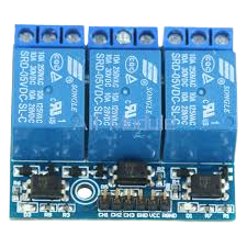
The Yongli 5V Relay 3 C is a 3-channel relay module designed for interfacing high-voltage devices with low-voltage microcontroller systems like Arduino, Raspberry Pi, or PIC. Each channel can control a separate device, making it suitable for a variety of applications such as home automation, industrial controls, and hobbyist projects.
Explore Projects Built with 3 Channel Relay 5V

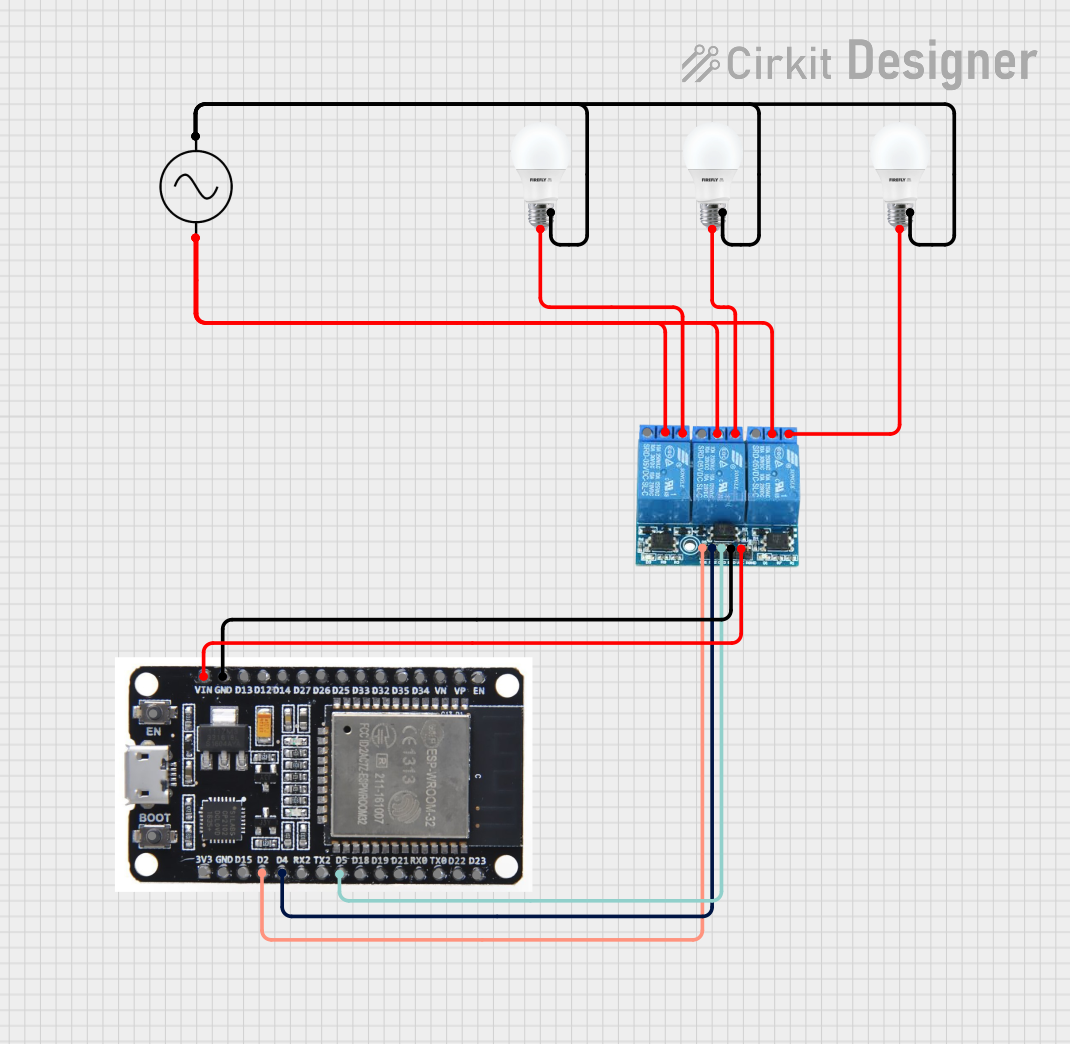

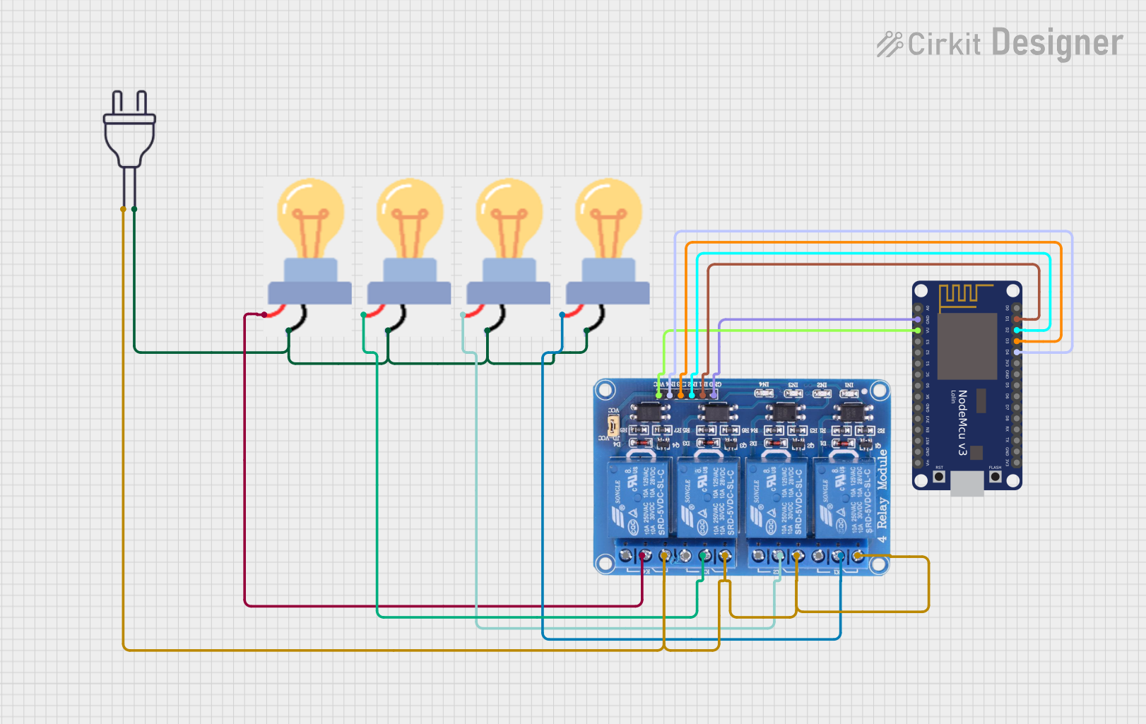
Explore Projects Built with 3 Channel Relay 5V
Common Applications and Use Cases
- Home automation systems
- Remote control of AC/DC motors
- Switching of high-power LEDs
- Control of pumps, fans, and other electrical appliances
Technical Specifications
Key Technical Details
- Operating Voltage: 5V DC
- Relay Maximum Switching Voltage: 250V AC / 30V DC
- Relay Maximum Switching Current: 10A (AC) / 10A (DC)
- Number of Channels: 3
- Control Signal: TTL Logic
- Isolation: Opto-isolated inputs
Pin Configuration and Descriptions
| Pin Number | Description | Type |
|---|---|---|
| 1 | IN1 (Input Signal 1) | Digital |
| 2 | IN2 (Input Signal 2) | Digital |
| 3 | IN3 (Input Signal 3) | Digital |
| 4 | GND (Ground) | Power |
| 5 | VCC (5V Input) | Power |
| 6-8 | COM (Common) | Power |
| 9-11 | NO (Normally Open) | Switch |
| 12-14 | NC (Normally Closed) | Switch |
Usage Instructions
How to Use the Component in a Circuit
- Connect the VCC pin to a 5V power supply.
- Connect the GND pin to the ground of the power supply.
- Connect the IN1, IN2, and IN3 pins to the digital output pins of a microcontroller.
- Connect the device you want to control to the NO or NC and COM pins of the relay.
Important Considerations and Best Practices
- Ensure the power supply does not exceed 5V as it may damage the relay module.
- Do not exceed the maximum switching voltage and current ratings of the relays.
- Use flyback diodes when controlling inductive loads to prevent back EMF damage.
- Always ensure proper isolation when working with high-voltage circuits.
Example Code for Arduino UNO
// Define relay control pins
const int relay1 = 2;
const int relay2 = 3;
const int relay3 = 4;

void setup() {
  // Set relay pins as outputs
  pinMode(relay1, OUTPUT);
  pinMode(relay2, OUTPUT);
  pinMode(relay3, OUTPUT);
}

void loop() {
  // Turn on relay 1
  digitalWrite(relay1, HIGH);
  delay(1000); // Wait for 1 second
  // Turn off relay 1
  digitalWrite(relay1, LOW);
  delay(1000); // Wait for 1 second

  // Repeat for relay 2 and 3
  digitalWrite(relay2, HIGH);
  delay(1000);
  digitalWrite(relay2, LOW);
  delay(1000);

  digitalWrite(relay3, HIGH);
  delay(1000);
  digitalWrite(relay3, LOW);
  delay(1000);
}
Troubleshooting and FAQs
Common Issues
- Relay not activating: Check the input signal and power connections.
- Intermittent operation: Ensure solid connections and no loose wires.
- Overheating: Do not exceed the rated current and voltage.
Solutions and Tips for Troubleshooting
- Verify that the 5V power supply is stable and within tolerance.
- Check for proper grounding in your circuit.
- Use a multimeter to confirm the control signal from the microcontroller.
- Ensure that the load does not exceed the relay's maximum ratings.
FAQs
Q: Can I control the relay module with a 3.3V microcontroller?
A: Yes, but ensure that the 3.3V signal is sufficient to trigger the relay. Check the module's datasheet for the minimum input signal voltage.
Q: Is it safe to control AC devices with this relay module?
A: Yes, as long as you do not exceed the maximum voltage and current ratings and ensure proper isolation and safety precautions.
Q: Can I use PWM to control the relay?
A: No, relays require a stable HIGH or LOW signal to switch states. PWM is not suitable for relay control.
Remember to always follow safety guidelines when working with electronics, especially when controlling high-voltage devices.