How to Use H-bridge Breakout Board: Examples, Pinouts, and Specs
Introduction
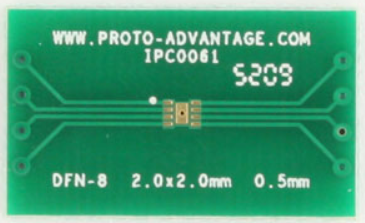
The H-bridge Breakout Board (Manufacturer: Proto Advantage, Part ID: IPC0061) is a versatile circuit board designed to control the direction and speed of DC motors. It utilizes an H-bridge configuration, which allows for bidirectional control of a motor by reversing the polarity of the voltage applied to it. This component is ideal for robotics, motorized projects, and other applications requiring precise motor control.
Explore Projects Built with H-bridge Breakout Board

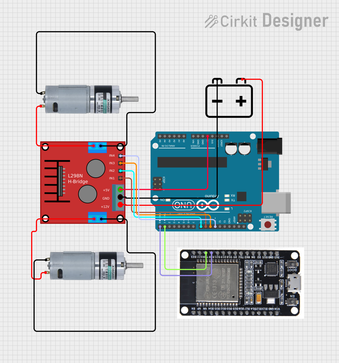
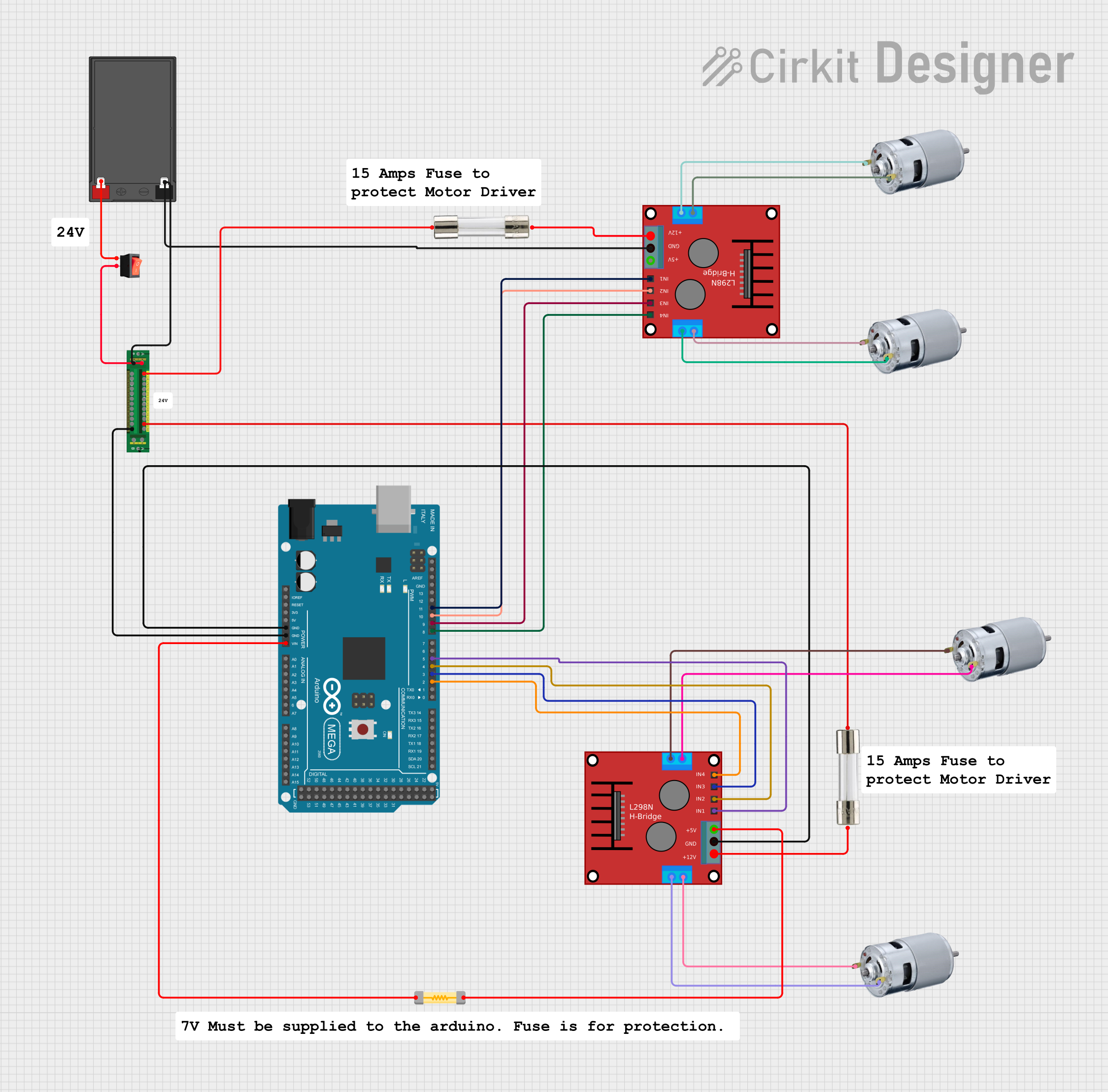
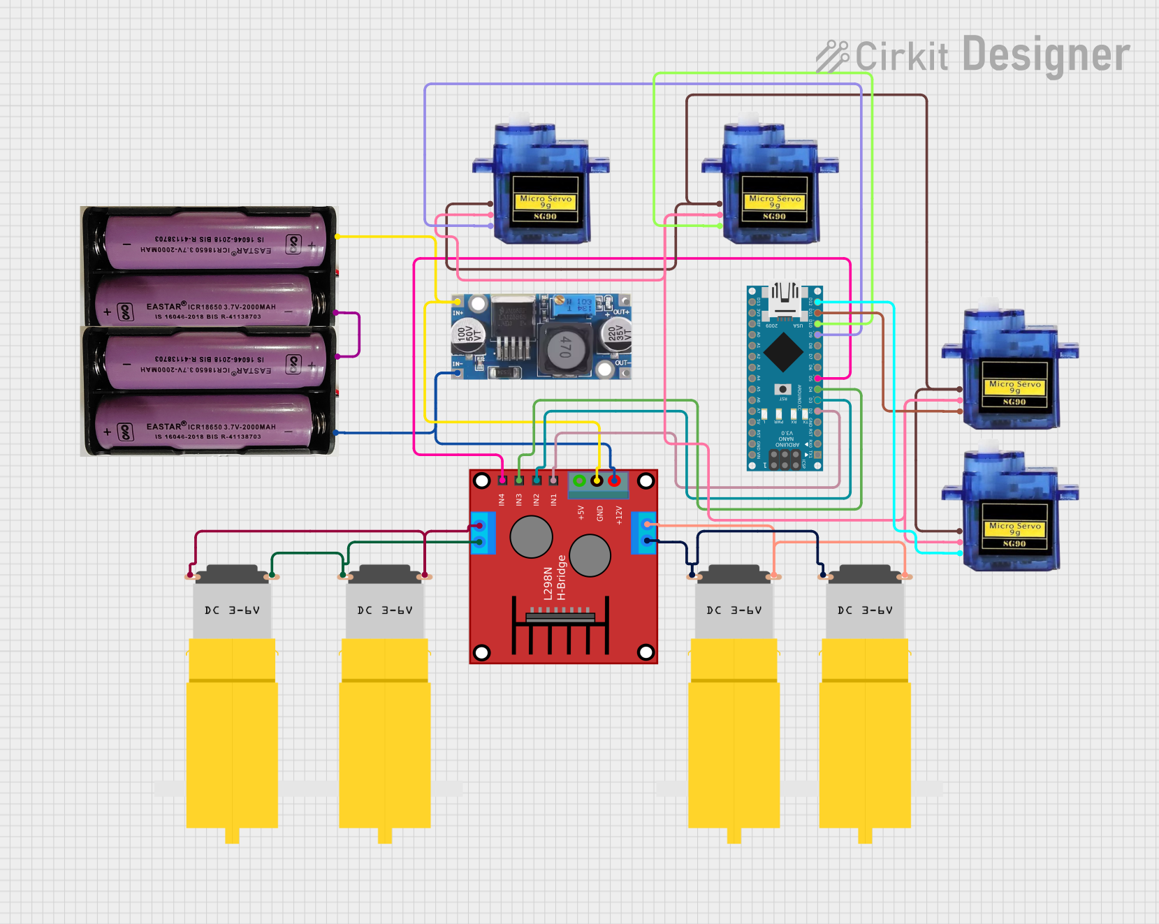
Explore Projects Built with H-bridge Breakout Board
Common Applications and Use Cases
- Robotics: Controlling the movement of robot wheels or arms.
- Motorized systems: Operating conveyor belts, fans, or small vehicles.
- DIY projects: Building remote-controlled cars or automated systems.
- Educational purposes: Teaching motor control concepts in electronics and engineering.
Technical Specifications
The following table outlines the key technical details of the H-bridge Breakout Board:
| Parameter | Value |
|---|---|
| Manufacturer | Proto Advantage |
| Part ID | IPC0061 |
| Operating Voltage | 5V to 12V |
| Maximum Current | 2A per channel |
| Motor Channels | 1 (single motor control) |
| Control Logic Voltage | 3.3V or 5V (compatible with most microcontrollers) |
| Dimensions | 30mm x 20mm x 10mm |
| Operating Temperature | -20°C to 85°C |
Pin Configuration and Descriptions
The H-bridge Breakout Board has the following pin layout:
| Pin Name | Type | Description |
|---|---|---|
| VCC | Power Input | Connect to the power supply (5V to 12V). |
| GND | Ground | Connect to the ground of the power supply. |
| IN1 | Control Input | Logic input to control motor direction (see usage). |
| IN2 | Control Input | Logic input to control motor direction (see usage). |
| EN | Enable Input | Enables or disables the motor (active HIGH). |
| OUT1 | Motor Output | Connect to one terminal of the DC motor. |
| OUT2 | Motor Output | Connect to the other terminal of the DC motor. |
Usage Instructions
How to Use the Component in a Circuit
- Power the Board: Connect the VCC pin to a power supply (5V to 12V) and the GND pin to the ground.
- Connect the Motor: Attach the two terminals of the DC motor to the OUT1 and OUT2 pins.
- Control Inputs:
- Use the IN1 and IN2 pins to control the motor's direction:
- IN1 = HIGH, IN2 = LOW: Motor rotates in one direction.
- IN1 = LOW, IN2 = HIGH: Motor rotates in the opposite direction.
- IN1 = LOW, IN2 = LOW: Motor stops (brake mode).
- IN1 = HIGH, IN2 = HIGH: Motor stops (brake mode).
- Use the EN pin to enable or disable the motor:
- EN = HIGH: Motor is enabled.
- EN = LOW: Motor is disabled.
- Use the IN1 and IN2 pins to control the motor's direction:
- Connect to a Microcontroller: Use a microcontroller (e.g., Arduino UNO) to send logic signals to the IN1, IN2, and EN pins for automated control.
Important Considerations and Best Practices
- Power Supply: Ensure the power supply voltage matches the motor's requirements and does not exceed the board's maximum voltage rating.
- Current Limit: Do not exceed the 2A current limit per channel to avoid damaging the board.
- Heat Dissipation: If operating at high currents, consider adding a heat sink or ensuring proper ventilation.
- Logic Voltage: Verify that the control logic voltage (3.3V or 5V) is compatible with your microcontroller.
Example Code for Arduino UNO
Below is an example Arduino sketch to control a DC motor using the H-bridge Breakout Board:
// Pin definitions
const int EN = 9;   // Enable pin connected to Arduino pin 9
const int IN1 = 7;  // IN1 pin connected to Arduino pin 7
const int IN2 = 8;  // IN2 pin connected to Arduino pin 8

void setup() {
  // Set pin modes
  pinMode(EN, OUTPUT);
  pinMode(IN1, OUTPUT);
  pinMode(IN2, OUTPUT);

  // Initialize motor in stopped state
  digitalWrite(EN, LOW);  // Disable motor
  digitalWrite(IN1, LOW); // Set IN1 to LOW
  digitalWrite(IN2, LOW); // Set IN2 to LOW
}

void loop() {
  // Example: Rotate motor in one direction for 2 seconds
  digitalWrite(EN, HIGH);  // Enable motor
  digitalWrite(IN1, HIGH); // Set IN1 to HIGH
  digitalWrite(IN2, LOW);  // Set IN2 to LOW
  delay(2000);             // Wait for 2 seconds

  // Example: Rotate motor in the opposite direction for 2 seconds
  digitalWrite(IN1, LOW);  // Set IN1 to LOW
  digitalWrite(IN2, HIGH); // Set IN2 to HIGH
  delay(2000);             // Wait for 2 seconds

  // Example: Stop the motor for 2 seconds
  digitalWrite(IN1, LOW);  // Set IN1 to LOW
  digitalWrite(IN2, LOW);  // Set IN2 to LOW
  delay(2000);             // Wait for 2 seconds
}
Troubleshooting and FAQs
Common Issues and Solutions
Motor Does Not Spin:
- Ensure the EN pin is set to HIGH to enable the motor.
- Verify that the power supply is connected and providing the correct voltage.
- Check the connections to the motor and ensure they are secure.
Motor Spins in the Wrong Direction:
- Swap the logic levels of IN1 and IN2 to reverse the motor's direction.
- Verify the motor's wiring to OUT1 and OUT2.
Board Overheats:
- Ensure the motor's current does not exceed 2A.
- Add a heat sink or improve ventilation if operating at high currents.
No Response from the Board:
- Check all connections, including power, ground, and control signals.
- Verify that the microcontroller is functioning and sending the correct logic levels.
FAQs
Q: Can I use this board to control two motors?
A: No, this breakout board is designed to control a single motor. For dual-motor control, consider using a dual H-bridge module.
Q: Is this board compatible with 3.3V logic microcontrollers?
A: Yes, the board is compatible with both 3.3V and 5V logic levels.
Q: Can I use this board with a stepper motor?
A: No, this board is designed for DC motors. For stepper motors, use a dedicated stepper motor driver.
Q: What happens if I set both IN1 and IN2 to HIGH?
A: The motor will enter brake mode and stop rotating.
By following this documentation, you can effectively use the Proto Advantage IPC0061 H-bridge Breakout Board in your projects.