How to Use ZVS Driver: Examples, Pinouts, and Specs
Introduction
A Zero Voltage Switching (ZVS) driver is a specialized circuit designed to enable efficient switching of power transistors, such as MOSFETs or IGBTs, by ensuring that they turn on and off at zero voltage. This minimizes switching losses, reduces heat generation, and improves overall efficiency. ZVS drivers are commonly used in high-frequency applications, including resonant converters, induction heating systems, wireless power transfer, and high-efficiency power supplies.
By operating at zero voltage during switching transitions, the ZVS driver significantly reduces electromagnetic interference (EMI) and extends the lifespan of the switching components.
Explore Projects Built with ZVS Driver

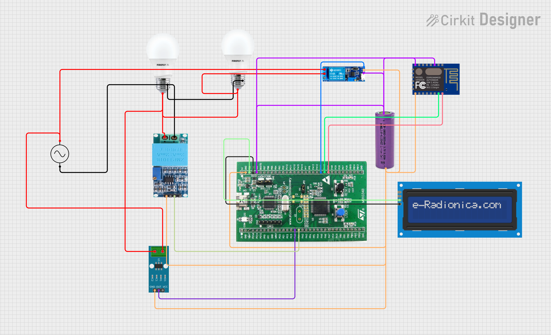
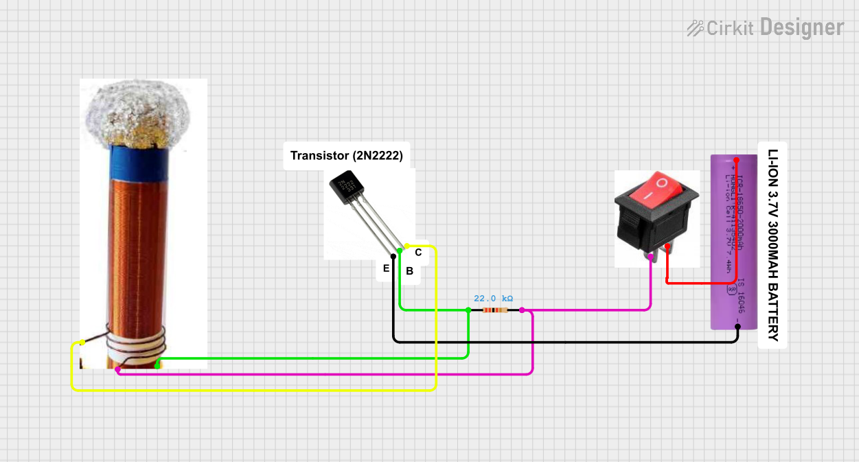
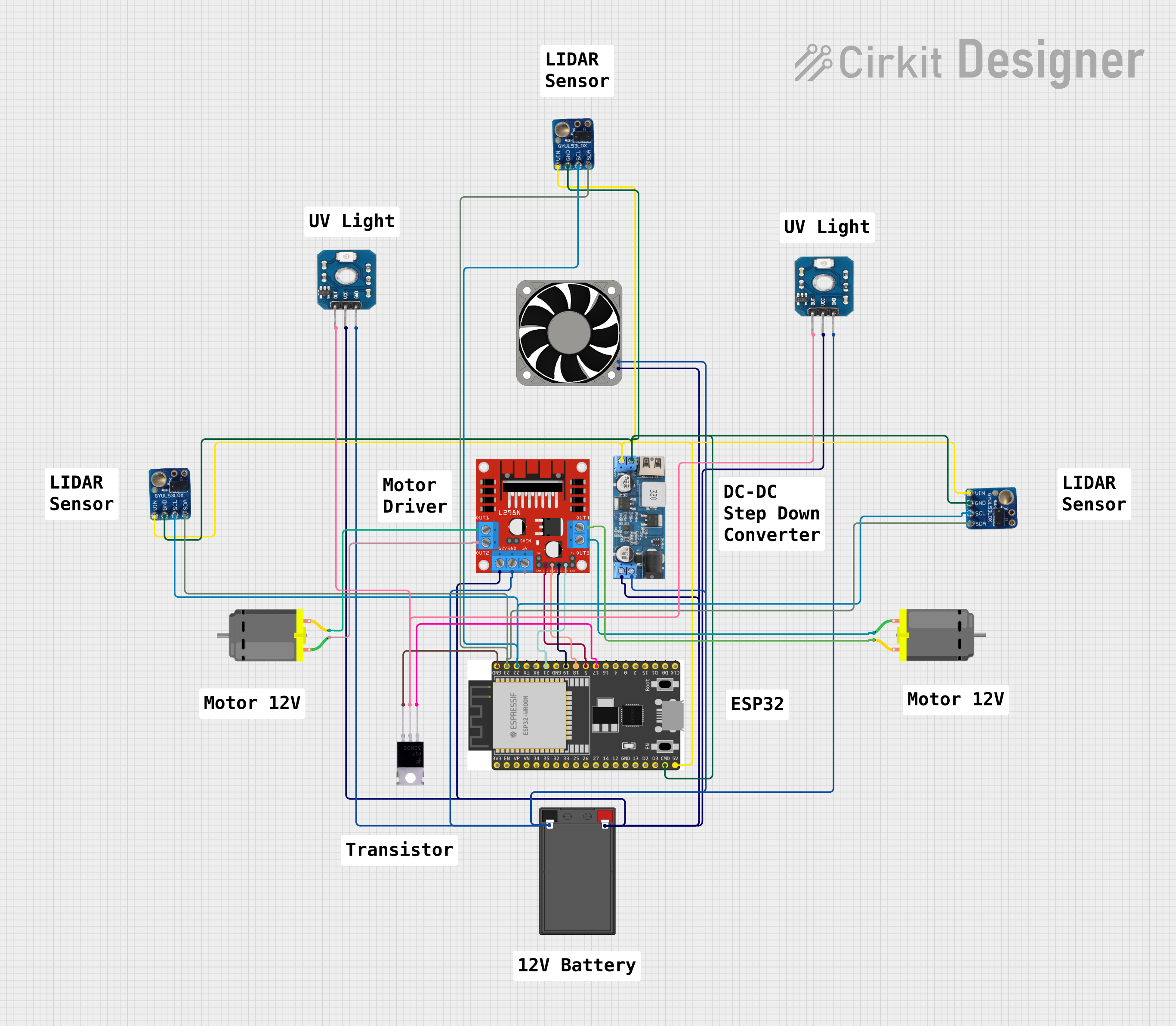
Explore Projects Built with ZVS Driver
Technical Specifications
Below are the key technical details of a typical ZVS driver module:
- Input Voltage Range: 12V to 36V DC
- Output Power: Up to 120W (depending on input voltage and load)
- Operating Frequency: 20 kHz to 1 MHz (varies with load and circuit design)
- Efficiency: >90% (under optimal conditions)
- Supported Load Types: Inductive loads (e.g., coils, transformers)
- Switching Method: Zero Voltage Switching (ZVS)
- Protection Features: Overcurrent protection (varies by design)
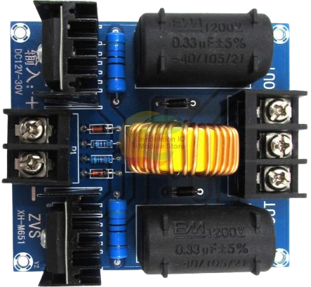
Pin Configuration and Descriptions
The ZVS driver module typically has the following pin configuration:
| Pin Name | Description |
|---|---|
| V+ | Positive DC input voltage (12V to 36V). Connect to the positive terminal of the power supply. |
| GND | Ground connection. Connect to the negative terminal of the power supply. |
| OUT+ | Positive output terminal. Connect to the load (e.g., coil or transformer). |
| OUT- | Negative output terminal. Connect to the other terminal of the load. |
Usage Instructions
How to Use the ZVS Driver in a Circuit
- Power Supply: Connect a DC power supply to the
V+andGNDpins. Ensure the voltage is within the specified range (12V to 36V). - Load Connection: Connect the load (e.g., an induction coil or transformer) to the
OUT+andOUT-terminals. Ensure the load is inductive and suitable for the operating frequency of the ZVS driver. - Heat Dissipation: Attach a heatsink to the MOSFETs on the ZVS driver module to prevent overheating during operation.
- Start-Up: Power on the DC supply. The ZVS driver will automatically start oscillating and drive the load at the resonant frequency.
Important Considerations and Best Practices
- Load Matching: Ensure the load is inductive and matches the operating frequency of the ZVS driver. Using a non-inductive load may damage the module.
- Power Supply: Use a stable DC power supply with sufficient current capacity to handle the load.
- Cooling: Always use a heatsink or active cooling for the MOSFETs to prevent thermal damage.
- Avoid Overvoltage: Do not exceed the maximum input voltage (36V) to avoid damaging the module.
- Wiring: Use thick wires for the power and load connections to minimize resistance and voltage drops.
Example: Using a ZVS Driver with an Arduino UNO
While the ZVS driver is not directly controlled by an Arduino, it can be used in conjunction with an Arduino to monitor or control the input voltage or load conditions. Below is an example code snippet to monitor the input voltage of the ZVS driver using an Arduino UNO:
// Arduino code to monitor the input voltage of a ZVS driver
// Connect the input voltage (V+) to an analog pin (e.g., A0) via a voltage divider

const int voltagePin = A0;  // Analog pin connected to the voltage divider
const float voltageDividerRatio = 10.0;  // Adjust based on your resistor values

void setup() {
  Serial.begin(9600);  // Initialize serial communication
  pinMode(voltagePin, INPUT);  // Set the voltage pin as input
}

void loop() {
  int analogValue = analogRead(voltagePin);  // Read the analog value
  float inputVoltage = (analogValue * 5.0 / 1023.0) * voltageDividerRatio;

  // Print the input voltage to the Serial Monitor
  Serial.print("Input Voltage: ");
  Serial.print(inputVoltage);
  Serial.println(" V");

  delay(1000);  // Wait for 1 second before the next reading
}
Note: Use a voltage divider to scale down the input voltage to a level safe for the Arduino's analog input pins (0-5V). For example, if the ZVS driver input voltage is 36V, use a 10:1 voltage divider.
Troubleshooting and FAQs
Common Issues and Solutions
No Oscillation or Output:
- Cause: Insufficient input voltage or incorrect load connection.
- Solution: Verify the input voltage is within the specified range and ensure the load is properly connected.
Overheating MOSFETs:
- Cause: Inadequate cooling or excessive load current.
- Solution: Attach a heatsink or use active cooling. Reduce the load current if necessary.
Low Efficiency:
- Cause: Mismatched load or poor wiring.
- Solution: Use an inductive load that matches the operating frequency. Ensure all connections are secure and use thick wires.
Module Damage:
- Cause: Overvoltage or short circuit.
- Solution: Ensure the input voltage does not exceed 36V. Check for short circuits in the wiring.
FAQs
Q: Can I use a resistive load with the ZVS driver?
A: No, the ZVS driver is designed for inductive loads. Using a resistive load may damage the module.Q: What type of power supply should I use?
A: Use a stable DC power supply with a voltage range of 12V to 36V and sufficient current capacity for your load.Q: How do I adjust the operating frequency?
A: The operating frequency is determined by the load and the circuit design. To change the frequency, modify the inductance or capacitance in the circuit.Q: Can I use the ZVS driver for wireless power transfer?
A: Yes, the ZVS driver is commonly used in wireless power transfer systems. Ensure the transmitter and receiver coils are properly tuned for resonance.
By following this documentation, you can effectively use the ZVS driver in your high-frequency applications while minimizing issues and maximizing efficiency.