
How to Use WIZ820io: Examples, Pinouts, and Specs
 Design with WIZ820io in Cirkit Designer
Introduction
The WIZ820io is an Ethernet module designed to provide a straightforward solution for connecting microcontrollers to the internet. It is built around the W5500 Ethernet chip, which includes a hardware TCP/IP stack, enabling efficient and reliable network communication. The module is compact, easy to integrate, and supports high-speed SPI communication, making it ideal for projects requiring internet connectivity.
Explore Projects Built with WIZ820io
 Open Project in Cirkit Designer
 Open Project in Cirkit Designer
 Open Project in Cirkit Designer
 Open Project in Cirkit Designer
Explore Projects Built with WIZ820io
Open Project in Cirkit DesignerOpen Project in Cirkit DesignerOpen Project in Cirkit DesignerOpen Project in Cirkit DesignerCommon Applications and Use Cases
- IoT (Internet of Things) devices
- Home automation systems
- Remote monitoring and control
- Data logging and cloud integration
- Network-enabled embedded systems
Technical Specifications
The WIZ820io module is designed for high performance and ease of use. Below are its key technical specifications:
| Parameter | Value |
|---|---|
| Ethernet Controller | W5500 |
| Communication Interface | SPI (Serial Peripheral Interface) |
| Operating Voltage | 3.3V |
| Current Consumption | 132mA (typical) |
| Network Protocols | TCP, UDP, IPv4, ICMP, ARP, IGMP |
| Data Transfer Rate | 10/100 Mbps |
| Dimensions | 23mm x 25mm |
| Operating Temperature | -40°C to +85°C |
Pin Configuration and Descriptions
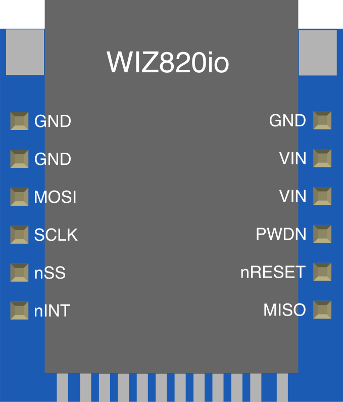
The WIZ820io module has a 2x6 pin header for interfacing with microcontrollers. Below is the pinout:
| Pin | Name | Description |
|---|---|---|
| 1 | GND | Ground connection |
| 2 | 3.3V | Power supply (3.3V) |
| 3 | SCLK | SPI clock input |
| 4 | MISO | SPI Master-In-Slave-Out (data output from WIZ820io) |
| 5 | MOSI | SPI Master-Out-Slave-In (data input to WIZ820io) |
| 6 | CS | SPI chip select (active low) |
| 7 | INT | Interrupt output (active low, optional use) |
| 8 | RST | Reset input (active low) |
| 9 | NC | Not connected |
| 10 | NC | Not connected |
| 11 | NC | Not connected |
| 12 | NC | Not connected |
Usage Instructions
How to Use the WIZ820io in a Circuit
- Power Supply: Connect the 3.3V pin to a regulated 3.3V power source and GND to ground.
- SPI Interface: Connect the SPI pins (SCLK, MISO, MOSI, and CS) to the corresponding SPI pins on your microcontroller.
- Reset: Optionally, connect the RST pin to a GPIO pin on your microcontroller for manual or software-controlled resets.
- Interrupt: If needed, connect the INT pin to a GPIO pin to handle interrupts from the module.
- Network Connection: Plug an Ethernet cable into the RJ45 jack on the module.
Important Considerations and Best Practices
- Ensure the power supply is stable and within the 3.3V range to avoid damaging the module.
- Use proper pull-up or pull-down resistors on the SPI lines if required by your microcontroller.
- Keep SPI connections as short as possible to minimize noise and signal degradation.
- Use a decoupling capacitor (e.g., 0.1µF) near the power pins for improved stability.
- Configure the SPI clock speed according to the W5500 datasheet (up to 80 MHz).
Example Code for Arduino UNO
Below is an example of how to use the WIZ820io with an Arduino UNO to establish a basic Ethernet connection:
#include <SPI.h>
#include <Ethernet.h>

// MAC address for the Ethernet module
byte mac[] = { 0xDE, 0xAD, 0xBE, 0xEF, 0xFE, 0xED };

// IP address for the device (adjust as needed)
IPAddress ip(192, 168, 1, 177);

// Initialize the Ethernet server on port 80
EthernetServer server(80);

void setup() {
  // Start the serial communication for debugging
  Serial.begin(9600);
  while (!Serial) {
    ; // Wait for the serial port to connect (for Leonardo boards)
  }

  // Start the Ethernet connection
  if (Ethernet.begin(mac) == 0) {
    Serial.println("Failed to configure Ethernet using DHCP");
    // If DHCP fails, use a static IP address
    Ethernet.begin(mac, ip);
  }

  // Print the assigned IP address
  Serial.print("IP Address: ");
  Serial.println(Ethernet.localIP());

  // Start the server
  server.begin();
}

void loop() {
  // Listen for incoming clients
  EthernetClient client = server.available();
  if (client) {
    Serial.println("New client connected");
    // Send a basic HTTP response
    client.println("HTTP/1.1 200 OK");
    client.println("Content-Type: text/html");
    client.println("Connection: close");
    client.println();
    client.println("<!DOCTYPE HTML>");
    client.println("<html>");
    client.println("<h1>Hello from WIZ820io!</h1>");
    client.println("</html>");
    delay(1); // Give the client time to receive the data
    client.stop(); // Close the connection
    Serial.println("Client disconnected");
  }
}
Notes:
- Replace the
macandipvalues with those suitable for your network. - Ensure the Ethernet library is installed in your Arduino IDE.
Troubleshooting and FAQs
Common Issues
No Ethernet Connection:
- Verify the Ethernet cable is securely connected to the module and the router/switch.
- Check the power supply voltage (3.3V) and ensure it is stable.
- Ensure the SPI connections are correct and match the microcontroller's SPI pins.
Module Not Responding:
- Confirm the CS pin is correctly configured in your code.
- Check if the RST pin is properly connected or pulled high if unused.
- Ensure the SPI clock speed is within the supported range.
DHCP Fails:
- Verify the router has DHCP enabled.
- Use a static IP address if DHCP is not available.
Tips for Troubleshooting
- Use a logic analyzer or oscilloscope to monitor SPI signals for debugging.
- Test the module with a known working example code to rule out software issues.
- Check the W5500 datasheet for detailed information on register configurations and troubleshooting.
By following this documentation, you should be able to successfully integrate the WIZ820io module into your projects and troubleshoot common issues effectively.