Cirkit Designer Logo
Cirkit Designer
Your all-in-one circuit design IDE
Home / 
Component Documentation

How to Use GT-521F52: Examples, Pinouts, and Specs

Image of GT-521F52
Cirkit Designer LogoDesign with GT-521F52 in Cirkit Designer

Introduction

The GT-521F52 is a sophisticated fingerprint recognition module that provides secure biometric authentication for a variety of applications. This module is known for its high accuracy and quick identification speed, making it an ideal choice for enhancing security in systems such as access control, time attendance terminals, and personal identification projects. Its compact design allows for easy integration into electronic systems, offering a reliable method for user verification.

Explore Projects Built with GT-521F52

Use Cirkit Designer to design, explore, and prototype these projects online. Some projects support real-time simulation. Click "Open Project" to start designing instantly!
RTL8720DN-Based Interactive Button-Controlled TFT Display
Image of coba-coba: A project utilizing GT-521F52 in a practical application
This circuit features an RTL8720DN microcontroller interfaced with a China ST7735S 160x128 TFT LCD display and four pushbuttons. The microcontroller reads the states of the pushbuttons and displays their statuses on the TFT LCD, providing a visual feedback system for button presses.
Cirkit Designer LogoOpen Project in Cirkit Designer
Arduino Mega 2560 Based Security System with Fingerprint Authentication and SMS Alerts
Image of Door security system: A project utilizing GT-521F52 in a practical application
This circuit features an Arduino Mega 2560 microcontroller interfaced with a SIM800L GSM module, two fingerprint scanners, an I2C LCD display, an IR sensor, and a piezo buzzer. Power management is handled by a PowerBoost 1000 Basic Pad USB, a TP4056 charging module, and a Li-ion 18650 battery, with an option to use a Mini AC-DC 110V-230V to 5V 700mA module for direct power supply. The primary functionality appears to be a security system with GSM communication capabilities, biometric access control, and visual/audible feedback.
Cirkit Designer LogoOpen Project in Cirkit Designer
Satellite-Based Timing and Navigation System with SDR and Atomic Clock Synchronization
Image of GPS 시스템 측정 구성도_Confirm: A project utilizing GT-521F52 in a practical application
This circuit appears to be a complex system involving power supply management, GPS and timing synchronization, and data communication. It includes a SI-TEX G1 Satellite Compass for GPS data, an XHTF1021 Atomic Rubidium Clock for precise timing, and Ettus USRP B200 units for software-defined radio communication. Power is supplied through various SMPS units and distributed via terminal blocks and DC jacks. Data communication is facilitated by Beelink MINI S12 N95 computers, RS232 splitters, and a 1000BASE-T Media Converter for network connectivity. RF Directional Couplers are used to interface antennas with the USRP units, and the entire system is likely contained within cases for protection and organization.
Cirkit Designer LogoOpen Project in Cirkit Designer
NFC-Enabled Access Control System with Time Logging
Image of doorlock: A project utilizing GT-521F52 in a practical application
This circuit is designed for access control with time tracking capabilities. It features an NFC/RFID reader for authentication, an RTC module (DS3231) for real-time clock functionality, and an OLED display for user interaction. A 12V relay controls a magnetic lock, which is activated upon successful NFC/RFID authentication, and a button switch is likely used for manual operation or input. The T8_S3 microcontroller serves as the central processing unit, interfacing with the NFC/RFID reader, RTC, OLED, and relay to manage the access control logic.
Cirkit Designer LogoOpen Project in Cirkit Designer

Explore Projects Built with GT-521F52

Use Cirkit Designer to design, explore, and prototype these projects online. Some projects support real-time simulation. Click "Open Project" to start designing instantly!
Image of coba-coba: A project utilizing GT-521F52 in a practical application
RTL8720DN-Based Interactive Button-Controlled TFT Display
This circuit features an RTL8720DN microcontroller interfaced with a China ST7735S 160x128 TFT LCD display and four pushbuttons. The microcontroller reads the states of the pushbuttons and displays their statuses on the TFT LCD, providing a visual feedback system for button presses.
Cirkit Designer LogoOpen Project in Cirkit Designer
Image of Door security system: A project utilizing GT-521F52 in a practical application
Arduino Mega 2560 Based Security System with Fingerprint Authentication and SMS Alerts
This circuit features an Arduino Mega 2560 microcontroller interfaced with a SIM800L GSM module, two fingerprint scanners, an I2C LCD display, an IR sensor, and a piezo buzzer. Power management is handled by a PowerBoost 1000 Basic Pad USB, a TP4056 charging module, and a Li-ion 18650 battery, with an option to use a Mini AC-DC 110V-230V to 5V 700mA module for direct power supply. The primary functionality appears to be a security system with GSM communication capabilities, biometric access control, and visual/audible feedback.
Cirkit Designer LogoOpen Project in Cirkit Designer
Image of GPS 시스템 측정 구성도_Confirm: A project utilizing GT-521F52 in a practical application
Satellite-Based Timing and Navigation System with SDR and Atomic Clock Synchronization
This circuit appears to be a complex system involving power supply management, GPS and timing synchronization, and data communication. It includes a SI-TEX G1 Satellite Compass for GPS data, an XHTF1021 Atomic Rubidium Clock for precise timing, and Ettus USRP B200 units for software-defined radio communication. Power is supplied through various SMPS units and distributed via terminal blocks and DC jacks. Data communication is facilitated by Beelink MINI S12 N95 computers, RS232 splitters, and a 1000BASE-T Media Converter for network connectivity. RF Directional Couplers are used to interface antennas with the USRP units, and the entire system is likely contained within cases for protection and organization.
Cirkit Designer LogoOpen Project in Cirkit Designer
Image of doorlock: A project utilizing GT-521F52 in a practical application
NFC-Enabled Access Control System with Time Logging
This circuit is designed for access control with time tracking capabilities. It features an NFC/RFID reader for authentication, an RTC module (DS3231) for real-time clock functionality, and an OLED display for user interaction. A 12V relay controls a magnetic lock, which is activated upon successful NFC/RFID authentication, and a button switch is likely used for manual operation or input. The T8_S3 microcontroller serves as the central processing unit, interfacing with the NFC/RFID reader, RTC, OLED, and relay to manage the access control logic.
Cirkit Designer LogoOpen Project in Cirkit Designer

Common Applications and Use Cases

  • Access control systems
  • Time and attendance systems
  • Safe boxes
  • Personal identification
  • User authentication for devices and software

Technical Specifications

Key Technical Details

  • Supply Voltage: 3.3 - 6.0 V
  • Supply Current: 130 mA typical
  • Peak Current: 140 mA
  • Fingerprint Capacity: 200 templates
  • Template Format: ISO/IEC 19794-2
  • Interface: UART (Universal Asynchronous Receiver/Transmitter)
  • Baud Rate: 9600 – 115200 bps (default 9600)
  • Image Resolution: 450 dpi
  • Effective Sensing Area: 15.5 mm x 18.0 mm
  • Scanning Speed: < 1 second
  • Matching Speed: < 1.5 seconds
  • Operating Temperature: -20°C to +50°C
  • Dimensions: 37.0 mm x 17.0 mm x 9.5 mm

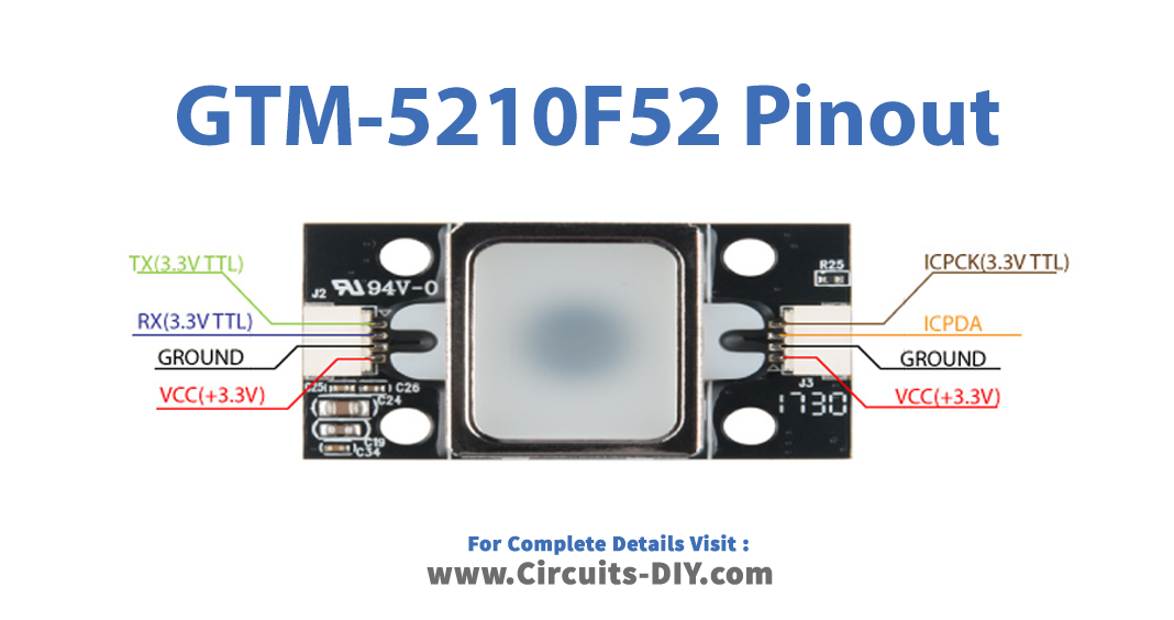
Pin Configuration and Descriptions

Pin Number Name Description
1 TXD Transmit Data (UART)
2 RXD Receive Data (UART)
3 GND Ground
4 VIN Input Voltage (3.3 - 6.0 V)

Usage Instructions

Integrating the GT-521F52 into a Circuit

  1. Power Supply: Connect the VIN pin to a 3.3V - 6.0V power source and the GND pin to the ground of your system.
  2. Data Communication: Connect the TXD and RXD pins to a UART interface. For Arduino UNO, connect the TXD pin of the GT-521F52 to the RX pin of the Arduino and the RXD pin to the TX pin.
  3. Initialization: Upon power-up, the module will initialize and be ready to accept commands via UART.

Important Considerations and Best Practices

  • Ensure that the power supply is stable and within the specified voltage range.
  • Avoid electrostatic discharge by grounding yourself before handling the module.
  • Keep the fingerprint sensor clean and free from scratches.
  • When enrolling fingerprints, ensure that the finger is placed correctly and consistently for accurate readings.
  • Use proper UART settings to match the module's default baud rate or the rate you have configured.

Example Code for Arduino UNO

#include <SoftwareSerial.h>

SoftwareSerial gtSerial(2, 3); // RX, TX

void setup() {
  gtSerial.begin(9600); // Start the software serial communication
  Serial.begin(9600);   // Start the hardware serial communication
}

void loop() {
  // Code to interact with the GT-521F52 module would go here.
  // This could include enrolling a new fingerprint, matching a fingerprint,
  // or deleting a fingerprint, depending on the application needs.
}

Troubleshooting and FAQs

Common Issues

  • Fingerprint Not Recognized: Ensure the finger is placed correctly on the sensor and that the sensor is clean.
  • Communication Error: Verify that the UART connections are correct and the baud rate matches the module's settings.
  • Module Not Powering Up: Check the power supply connections and ensure the voltage is within the specified range.

Solutions and Tips for Troubleshooting

  • Sensor Cleaning: Use a soft, dry cloth to gently wipe the sensor surface.
  • Baud Rate Configuration: If you have changed the default baud rate, ensure that your microcontroller's UART settings match the new rate.
  • Power Supply Issues: If using batteries, ensure they are charged and capable of delivering the required current.

FAQs

Q: Can the GT-521F52 store fingerprint templates? A: Yes, it can store up to 200 templates.

Q: What is the default baud rate for communication? A: The default baud rate is 9600 bps.

Q: Can I use the GT-521F52 with a 5V system? A: Yes, the module can handle an input voltage from 3.3V to 6.0V.

Q: How do I enroll a new fingerprint? A: Enrolling a fingerprint involves sending specific commands via UART to the module to enter enrollment mode, then following the prompts to place the finger on the sensor multiple times for accurate reading.

Q: How can I increase the recognition speed? A: Recognition speed is generally fixed, but ensuring clean sensor contact and proper finger placement can help achieve optimal performance.

This documentation provides a comprehensive overview of the GT-521F52 fingerprint module, ensuring users can effectively integrate and utilize this component in their security applications. For further assistance or technical support, please refer to the manufacturer's resources or contact technical support.