
How to Use PICAXE-28: Examples, Pinouts, and Specs
 Design with PICAXE-28 in Cirkit Designer
Introduction
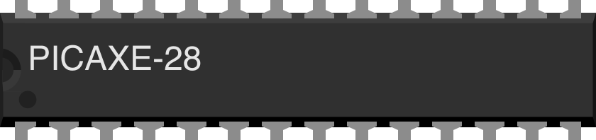
The PICAXE-28 is a microcontroller development board featuring a 28-pin PICAXE chip. It is designed for ease of programming and prototyping, making it an excellent choice for beginners and hobbyists. The PICAXE-28 is widely used in educational environments and DIY projects to control electronic devices, sensors, and actuators. Its simplicity and versatility make it a popular tool for learning programming and electronics.
Explore Projects Built with PICAXE-28
 Open Project in Cirkit Designer
 Open Project in Cirkit Designer
 Open Project in Cirkit Designer
 Open Project in Cirkit Designer
Explore Projects Built with PICAXE-28
Open Project in Cirkit DesignerOpen Project in Cirkit DesignerOpen Project in Cirkit DesignerOpen Project in Cirkit DesignerCommon Applications:
- Robotics and automation projects
- Sensor data acquisition and processing
- Motor control systems
- Educational programming exercises
- Home automation and IoT prototypes
Technical Specifications
The PICAXE-28 microcontroller board is built around a PICAXE chip, which is preloaded with a BASIC interpreter for easy programming. Below are the key technical details:
Key Specifications:
- Operating Voltage: 4.5V to 5.5V
- Clock Speed: 4 MHz (internal resonator)
- I/O Pins: 22 (16 digital, 6 analog)
- Programming Language: PICAXE BASIC
- Memory:
- 256 bytes of EEPROM
- 2048 bytes of program memory
- Communication Protocols: Serial (via programming cable)
- Power Supply Options: Battery or regulated DC supply
- Current Consumption: ~2 mA (active), ~50 µA (sleep mode)
Pin Configuration and Descriptions:
The PICAXE-28 has a 28-pin layout. Below is the pin configuration:
| Pin Number | Pin Name | Function |
|---|---|---|
| 1 | V+ | Positive power supply (4.5V–5.5V) |
| 2 | Serial In | Serial programming input |
| 3 | Serial Out | Serial programming output |
| 4–11 | I/O 0–7 | General-purpose digital I/O pins |
| 12 | GND | Ground |
| 13–18 | I/O 8–13 | General-purpose digital I/O pins |
| 19–22 | ADC 0–3 | Analog-to-digital converter inputs |
| 23–28 | Reserved | Reserved for advanced functions |
Usage Instructions
How to Use the PICAXE-28 in a Circuit:
Powering the Board:
- Connect a 4.5V–5.5V DC power supply to the V+ and GND pins.
- Alternatively, use a 3xAA battery pack for portable applications.
Programming the PICAXE-28:
- Install the PICAXE Programming Editor software on your computer.
- Connect the PICAXE-28 to your computer using a PICAXE USB programming cable.
- Write your program in PICAXE BASIC and upload it to the microcontroller.
Connecting Peripherals:
- Use the I/O pins to connect LEDs, sensors, motors, or other devices.
- For analog sensors, connect them to the ADC pins (ADC 0–3).
Running the Program:
- Once the program is uploaded, the PICAXE-28 will execute it automatically.
- Use the serial output pin to monitor data or debug your program.
Important Considerations:
- Always ensure the power supply voltage is within the specified range to avoid damaging the microcontroller.
- Use pull-up or pull-down resistors for unused input pins to prevent floating states.
- Avoid drawing excessive current from the I/O pins (maximum 20 mA per pin).
Example Code for Arduino-like Functionality:
Below is an example of a simple program to blink an LED connected to I/O pin 0:
' Blink an LED connected to I/O pin 0
' Ensure the LED has a current-limiting resistor (e.g., 330 ohms)

main:
    high 0          ' Turn on the LED
    pause 1000      ' Wait for 1 second
    low 0           ' Turn off the LED
    pause 1000      ' Wait for 1 second
    goto main       ' Repeat the loop
Interfacing with Sensors:
To read an analog sensor connected to ADC 0, use the following code:
' Read an analog sensor connected to ADC 0 and display the value via serial

symbol sensorValue = b0  ' Define a variable to store the sensor value

main:
    readadc 0, sensorValue  ' Read the analog value from ADC 0
    sertxd ("Sensor Value: ", #sensorValue, 13, 10)  ' Send value via serial
    pause 500              ' Wait for 500 ms
    goto main              ' Repeat the loop
Troubleshooting and FAQs
Common Issues and Solutions:
The PICAXE-28 is not responding to programming commands:
- Ensure the programming cable is securely connected to both the computer and the PICAXE-28.
- Verify that the correct COM port is selected in the programming software.
- Check the power supply to ensure the board is powered on.
The program is not running after upload:
- Confirm that the program was successfully uploaded without errors.
- Ensure the correct pins are used for connecting peripherals.
Analog readings are inconsistent:
- Use a decoupling capacitor (e.g., 0.1 µF) between the ADC pin and GND to reduce noise.
- Verify that the sensor is properly connected and powered.
The microcontroller overheats:
- Check for short circuits or excessive current draw from the I/O pins.
- Ensure the power supply voltage does not exceed 5.5V.
FAQs:
Q: Can I use the PICAXE-28 with an external clock?
A: Yes, the PICAXE-28 supports external clock sources, but the default internal 4 MHz resonator is sufficient for most applications.
Q: What is the maximum current output of the I/O pins?
A: Each I/O pin can source or sink up to 20 mA, with a total maximum current of 90 mA for all pins combined.
Q: Can I use the PICAXE-28 for wireless communication?
A: Yes, you can interface the PICAXE-28 with wireless modules like Bluetooth or RF transceivers using the serial communication pins.
Q: Is the PICAXE-28 compatible with Arduino shields?
A: No, the PICAXE-28 is not directly compatible with Arduino shields due to differences in pin layout and functionality.
By following this documentation, you can effectively use the PICAXE-28 for a wide range of projects and applications.