How to Use PowerBoost 1000 Basic JST Pad: Examples, Pinouts, and Specs
Introduction
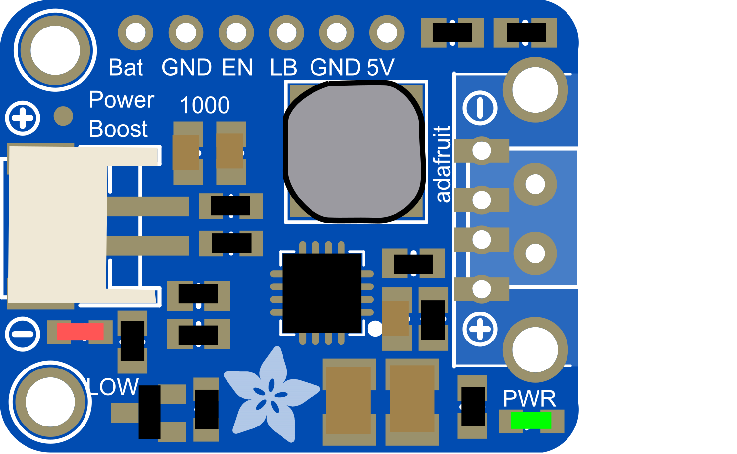
The PowerBoost 1000 Basic JST Pad is a versatile and compact electronic component designed to step up voltage to a regulated 5V output at up to 1A of current. This makes it an ideal choice for powering 5V USB-powered devices from a lower voltage source, such as a lithium polymer (LiPo) battery. The JST connector pad version allows for seamless integration into custom PCB designs, providing a reliable power solution for portable electronics, wearables, and IoT devices.
Explore Projects Built with PowerBoost 1000 Basic JST Pad
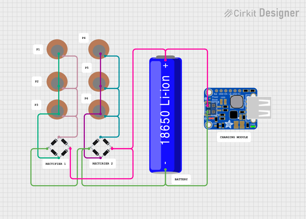

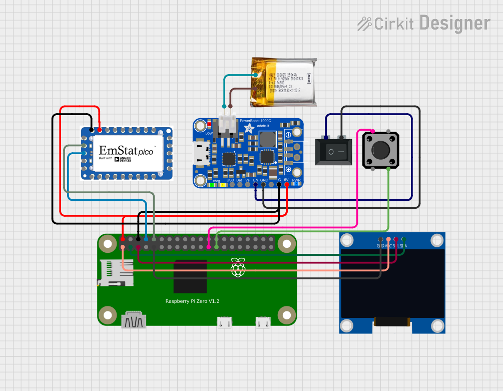

Explore Projects Built with PowerBoost 1000 Basic JST Pad
Common Applications and Use Cases
- Portable USB chargers
- Battery-powered electronics
- Wearable devices
- IoT projects
- Arduino-based projects
Technical Specifications
Key Technical Details
- Input Voltage: 3.7V nominal (suitable for LiPo batteries)
- Output Voltage: 5V regulated
- Output Current: Up to 1A
- Efficiency: 90% typical at full load
- Quiescent Current: <5mA
- Switching Frequency: 1.2MHz
Pin Configuration and Descriptions
| Pin Name | Description |
|---|---|
| VIN | Input voltage (3.7V nominal) |
| GND | Ground connection |
| 5V | Regulated 5V output |
| EN | Enable pin (active high) |
| BAT | Battery connection for monitoring |
Usage Instructions
How to Use the Component in a Circuit
- Power Source Connection: Connect a 3.7V LiPo battery to the VIN and GND pads.
- Output Connection: Connect the 5V and GND pads to the power input of your device.
- Enable Pin: If you wish to control the power output, connect the EN pin to a digital output on a microcontroller. Set the pin high to enable the boost converter.
Important Considerations and Best Practices
- Ensure that the input voltage does not exceed the maximum rating to prevent damage.
- The output current should not exceed 1A to maintain optimal performance.
- For noise-sensitive applications, additional filtering capacitors may be added at the output.
- Keep the power paths as short as possible to minimize losses.
- Avoid placing heat-sensitive components near the PowerBoost 1000 Basic as it may generate heat during operation.
Troubleshooting and FAQs
Common Issues
- Insufficient Output Voltage: Check the input voltage and load current. Ensure the input voltage is within the specified range and the load does not exceed 1A.
- Overheating: Reduce the load if the PowerBoost 1000 Basic is too hot. Ensure adequate ventilation around the component.
- No Output: Verify that the EN pin is set high if used. Check all connections for proper soldering and continuity.
Solutions and Tips for Troubleshooting
- Input Voltage Check: Use a multimeter to verify the input voltage at the VIN pad.
- Output Voltage Measurement: Measure the output voltage at the 5V pad to ensure it is a steady 5V.
- Connection Inspection: Inspect all solder joints and wiring connections for any signs of a poor connection or short circuit.
FAQs
Q: Can I use the PowerBoost 1000 Basic to charge a smartphone? A: Yes, as long as the device charges via 5V and does not draw more than 1A.
Q: Is it possible to disable the PowerBoost 1000 Basic when not in use? A: Yes, you can connect the EN pin to a digital output of a microcontroller and set it low to disable the boost converter.
Q: How can I integrate the PowerBoost 1000 Basic into my PCB design? A: The pad version is designed for direct soldering onto a PCB. Ensure your PCB layout matches the pad configuration and spacing of the PowerBoost 1000 Basic.
Q: What should I do if the PowerBoost 1000 Basic is not boosting the voltage correctly? A: Check the input voltage, load current, and ensure the EN pin is set high if used. Also, inspect the component for any signs of damage.
Example Arduino Code
// Example code to enable and disable the PowerBoost 1000 Basic using an Arduino UNO

const int enablePin = 9; // Connect to the EN pin of the PowerBoost 1000 Basic

void setup() {
  pinMode(enablePin, OUTPUT);
  // Start with the PowerBoost 1000 Basic enabled
  digitalWrite(enablePin, HIGH);
}

void loop() {
  // Enable the PowerBoost 1000 Basic
  digitalWrite(enablePin, HIGH);
  delay(5000); // Keep it on for 5 seconds

  // Disable the PowerBoost 1000 Basic
  digitalWrite(enablePin, LOW);
  delay(5000); // Keep it off for 5 seconds
}
This example demonstrates how to control the PowerBoost 1000 Basic using an Arduino UNO. The enablePin is connected to the EN pin of the PowerBoost, allowing the Arduino to turn the power on and off.