How to Use max30102: Examples, Pinouts, and Specs
Introduction
The MAX30102 is a pulse oximeter and heart-rate sensor module designed for non-invasive health monitoring. It uses photoplethysmography (PPG) to measure blood oxygen saturation (SpO2) and heart rate by analyzing light absorption changes in blood vessels. The module integrates an LED driver, photodetector, and ambient light rejection circuitry, ensuring accurate and reliable measurements even in challenging environments.
Explore Projects Built with max30102


Explore Projects Built with max30102
Common Applications and Use Cases
- Wearable health monitoring devices (e.g., fitness trackers, smartwatches)
- Medical devices for SpO2 and heart rate monitoring
- Research and development in biomedical engineering
- IoT-based health monitoring systems
- Sports and fitness applications
Technical Specifications
The MAX30102 is a compact and efficient sensor module with the following key specifications:
| Parameter | Value |
|---|---|
| Operating Voltage | 1.8V (core) and 3.3V (I/O) |
| Supply Current | 600 µA (typical) |
| LED Wavelengths | Red: 660 nm, Infrared: 880 nm |
| Communication Interface | I2C (7-bit address: 0x57) |
| Sampling Rate | Configurable (up to 1000 samples per second) |
| Operating Temperature Range | -40°C to +85°C |
| Dimensions | 5.6 mm x 3.3 mm x 1.55 mm |
Pin Configuration and Descriptions
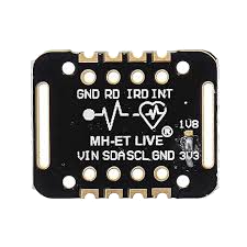
The MAX30102 module typically comes with the following pinout:
| Pin Name | Description |
|---|---|
| VIN | Power supply input (3.3V) |
| GND | Ground |
| SDA | I2C data line |
| SCL | I2C clock line |
| INT | Interrupt output (active low, optional use) |
Usage Instructions
How to Use the MAX30102 in a Circuit
- Power Supply: Connect the
VINpin to a 3.3V power source and theGNDpin to ground. - I2C Communication: Connect the
SDAandSCLpins to the corresponding I2C pins on your microcontroller (e.g., Arduino UNO: A4 for SDA, A5 for SCL). - Interrupt Pin (Optional): The
INTpin can be used to detect events like new data availability. If unused, leave it unconnected. - Pull-Up Resistors: Ensure that the I2C lines (SDA and SCL) have pull-up resistors (typically 4.7 kΩ) if not already present on the module.
Important Considerations and Best Practices
- Ambient Light: Avoid exposing the sensor to direct sunlight or strong ambient light, as it may interfere with measurements.
- Placement: For accurate readings, ensure the sensor is in close contact with the skin (e.g., fingertip or earlobe).
- Power Management: Use the sensor's low-power modes to conserve energy in battery-powered applications.
- I2C Address: The default I2C address of the MAX30102 is
0x57. Ensure no address conflicts if multiple I2C devices are used.
Example Code for Arduino UNO
Below is an example of how to interface the MAX30102 with an Arduino UNO to read heart rate and SpO2 data. This code uses the SparkFun MAX3010x library, which can be installed via the Arduino Library Manager.
#include <Wire.h>
#include "MAX30105.h" // Include the SparkFun MAX3010x library

MAX30105 particleSensor; // Create an instance of the MAX30105 class

void setup() {
  Serial.begin(9600); // Initialize serial communication at 9600 baud
  Serial.println("Initializing MAX30102...");

  // Initialize the MAX30102 sensor
  if (!particleSensor.begin()) {
    Serial.println("MAX30102 not detected. Please check wiring/power.");
    while (1); // Halt execution if the sensor is not found
  }

  // Configure the sensor for SpO2 and heart rate measurement
  particleSensor.setup(); // Default settings
  particleSensor.setPulseAmplitudeRed(0x0A); // Set red LED brightness
  particleSensor.setPulseAmplitudeIR(0x0A);  // Set IR LED brightness
}

void loop() {
  // Read raw data from the sensor
  long redValue = particleSensor.getRed(); // Red light data
  long irValue = particleSensor.getIR();   // Infrared light data

  // Print the raw data to the serial monitor
  Serial.print("Red: ");
  Serial.print(redValue);
  Serial.print(" IR: ");
  Serial.println(irValue);

  delay(100); // Wait 100 ms before the next reading
}
Notes:
- Ensure the MAX30102 module is properly connected to the Arduino UNO.
- Use a 3.3V power supply for the sensor to avoid damage.
- The
getRed()andgetIR()functions return raw PPG data, which can be processed further to calculate SpO2 and heart rate.
Troubleshooting and FAQs
Common Issues and Solutions
Sensor Not Detected
- Cause: Incorrect wiring or power supply.
- Solution: Verify the connections and ensure the sensor is powered with 3.3V. Check the I2C address (
0x57) and ensure no conflicts with other devices.
Inaccurate Readings
- Cause: Poor sensor placement or excessive ambient light.
- Solution: Ensure the sensor is in close contact with the skin and shield it from strong ambient light.
No Data Output
- Cause: Library not installed or incorrect initialization.
- Solution: Install the SparkFun MAX3010x library and ensure the
begin()function is called in thesetup()section.
I2C Communication Errors
- Cause: Missing pull-up resistors or incorrect I2C connections.
- Solution: Add 4.7 kΩ pull-up resistors to the SDA and SCL lines if not already present.
FAQs
Q: Can the MAX30102 measure SpO2 and heart rate simultaneously?
A: Yes, the MAX30102 can measure both parameters simultaneously by analyzing red and infrared light absorption.
Q: What is the maximum sampling rate of the MAX30102?
A: The MAX30102 supports a configurable sampling rate of up to 1000 samples per second.
Q: Can the MAX30102 be used with a 5V microcontroller?
A: Yes, but you must use a logic level shifter for the I2C lines, as the MAX30102 operates at 3.3V logic levels.
Q: Is the MAX30102 suitable for medical-grade applications?
A: While the MAX30102 is highly accurate, it is primarily designed for consumer-grade applications and may not meet medical certification standards.