Cirkit Designer
Your all-in-one circuit design IDE
Home /
Component Documentation
How to Use 7-Segment Panel Voltmeter: Examples, Pinouts, and Specs
Introduction
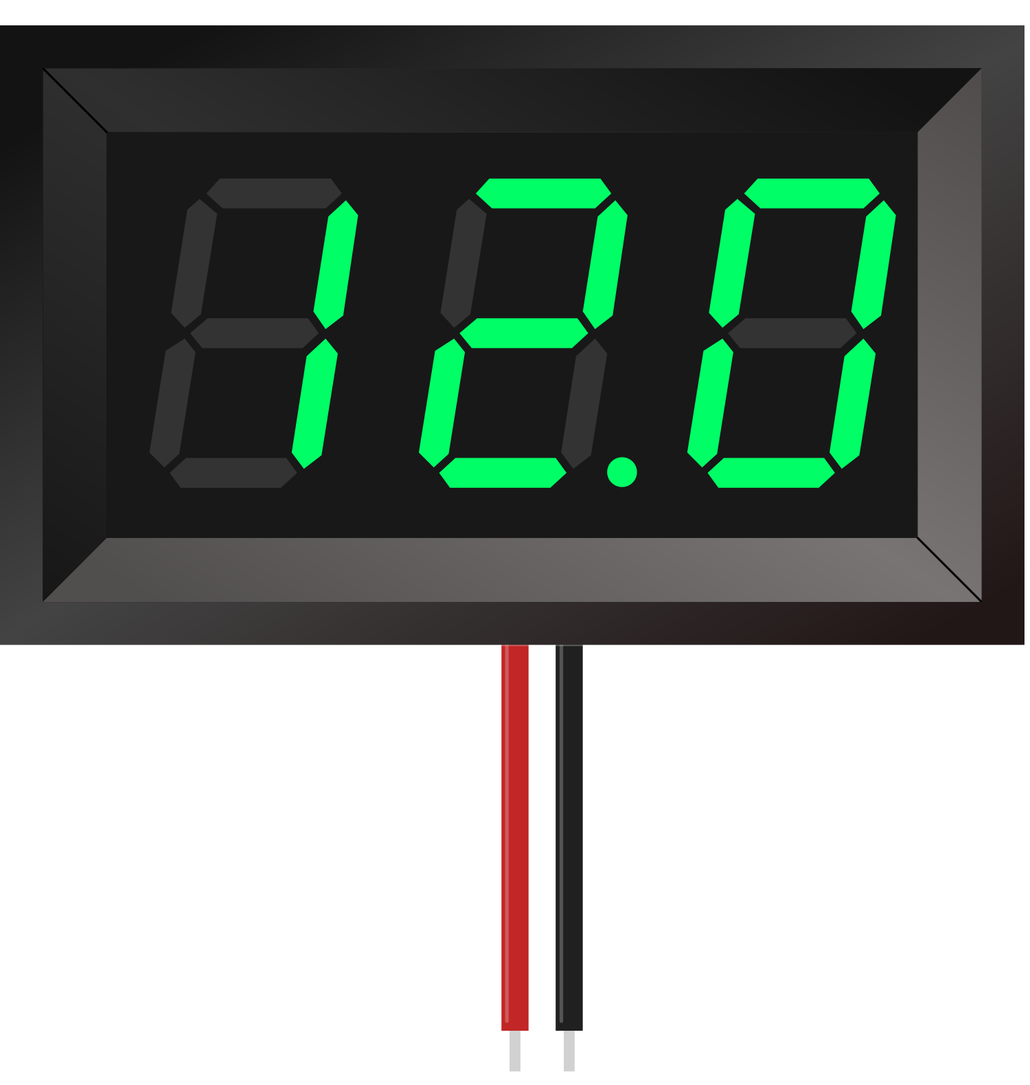
A 7-Segment Panel Voltmeter is an electronic device designed to measure and display voltage levels in an electrical circuit. It consists of a 7-segment LED or LCD display that provides a visual representation of the voltage reading. These voltmeters are commonly used in power supplies, battery monitors, and other applications where voltage monitoring is essential.
Explore Projects Built with 7-Segment Panel Voltmeter
7-Segment Voltmeter Display Circuit
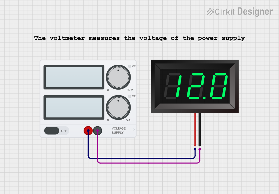
This circuit consists of a power supply connected to a 7-segment panel voltmeter, providing the necessary voltage and ground connections for the voltmeter to operate. The voltmeter is designed to display voltage readings, indicating the electrical potential difference in the circuit.
Battery-Powered LED Circuit with Toggle Switch and Voltmeter
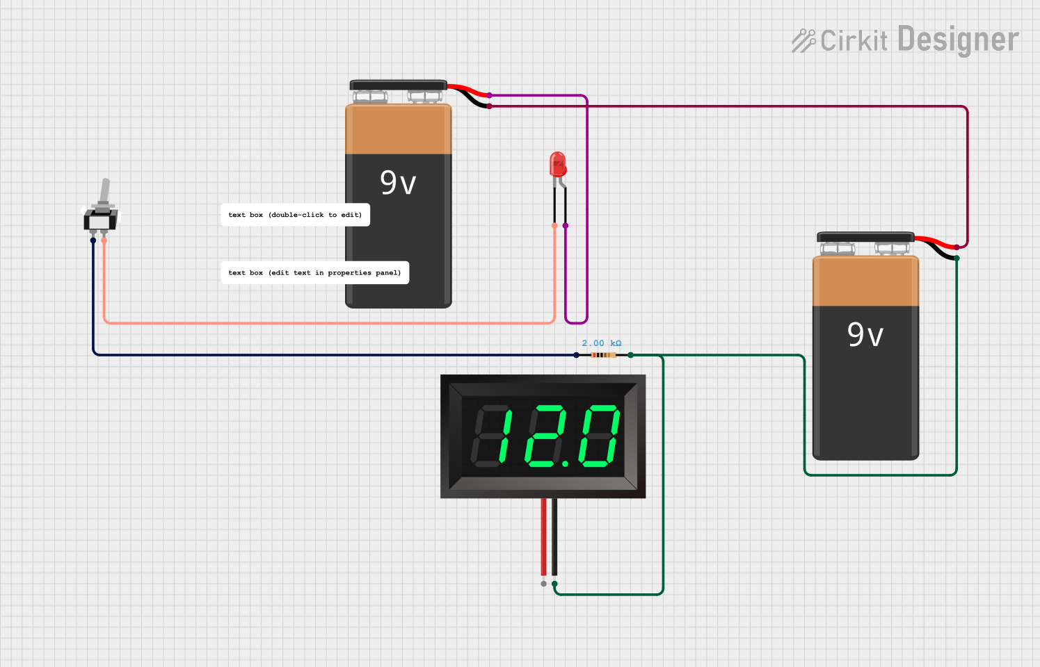
This circuit consists of a 9V battery powering a red LED through a 2k Ohm resistor and a toggle switch. Additionally, a 7-segment panel voltmeter is connected across the battery to display the voltage.
Arduino UNO Controlled Relay with Buzzer and Voltmeter
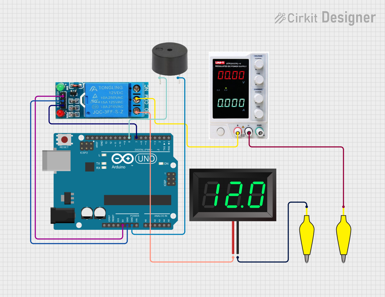
This circuit uses an Arduino UNO to control a 12V single-channel relay, which in turn powers a 7-segment panel voltmeter. Additionally, the Arduino controls a buzzer connected to digital pin D8. The relay is activated via digital pin D7 of the Arduino, and the entire system is powered by an external power supply.
Battery-Powered Li-ion Charger with Digital Volt/Ammeter and Buzzer Alert

This circuit is a battery charging and monitoring system for a Li-ion battery using a TP4056 charger module. It includes a digital volt/ammeter to display the battery voltage and current, and features LEDs and a piezo buzzer for status indication. The circuit also incorporates switches for controlling the power and monitoring functions.
Explore Projects Built with 7-Segment Panel Voltmeter
7-Segment Voltmeter Display Circuit
This circuit consists of a power supply connected to a 7-segment panel voltmeter, providing the necessary voltage and ground connections for the voltmeter to operate. The voltmeter is designed to display voltage readings, indicating the electrical potential difference in the circuit.
Battery-Powered LED Circuit with Toggle Switch and Voltmeter
This circuit consists of a 9V battery powering a red LED through a 2k Ohm resistor and a toggle switch. Additionally, a 7-segment panel voltmeter is connected across the battery to display the voltage.
Arduino UNO Controlled Relay with Buzzer and Voltmeter
This circuit uses an Arduino UNO to control a 12V single-channel relay, which in turn powers a 7-segment panel voltmeter. Additionally, the Arduino controls a buzzer connected to digital pin D8. The relay is activated via digital pin D7 of the Arduino, and the entire system is powered by an external power supply.
Battery-Powered Li-ion Charger with Digital Volt/Ammeter and Buzzer Alert
This circuit is a battery charging and monitoring system for a Li-ion battery using a TP4056 charger module. It includes a digital volt/ammeter to display the battery voltage and current, and features LEDs and a piezo buzzer for status indication. The circuit also incorporates switches for controlling the power and monitoring functions.
Common Applications and Use Cases
- Monitoring battery voltage in vehicles and portable devices
- Displaying power supply voltages in electronic equipment
- Measuring voltage in DIY electronics projects
- Educational tools for teaching electronics
Technical Specifications
Key Technical Details
- Voltage Range: Typically 0V to 30V DC (may vary by model)
- Resolution: 0.1V or 0.01V (depending on the model)
- Display Type: 7-segment LED/LCD
- Accuracy: ±1% (varies by model)
- Operating Temperature: -10°C to 65°C
Pin Configuration and Descriptions
| Pin Number | Description | Notes |
|---|---|---|
| 1 | Positive Voltage In | Connect to the positive voltage |
| 2 | Ground | Connect to the system ground |
| 3 | Decimal Point Control | Ground to activate (optional) |
Usage Instructions
How to Use the Component in a Circuit
- Power Connections: Connect the positive voltage input (Pin 1) to the point in the circuit where you want to measure the voltage. Connect the ground pin (Pin 2) to the common ground of the circuit.
- Decimal Point: If your voltmeter has a decimal point control (Pin 3), you can connect it to ground to activate the decimal point, if needed.
- Mounting: Secure the voltmeter panel in a suitable location where the display is visible.
Important Considerations and Best Practices
- Ensure that the voltage being measured does not exceed the voltmeter's maximum rating to avoid damage.
- Double-check all connections before powering up the circuit to prevent short circuits.
- If the voltmeter is to be used in a permanent installation, consider using a voltage regulator to protect against voltage spikes.
Troubleshooting and FAQs
Common Issues Users Might Face
- Display Not Lighting Up: Check the power connections and ensure the voltage is within the specified range.
- Inaccurate Readings: Verify that there are no loose connections and recalibrate the voltmeter if necessary.
- Fluctuating Readings: Ensure that the input voltage is stable and not subject to interference or noise.
Solutions and Tips for Troubleshooting
- If the display is dim or flickering, check the power supply for adequate current and stable voltage.
- For persistent inaccuracies, consult the voltmeter's calibration procedure as outlined in the manufacturer's manual.
- Use shielded cables for the voltage input if the environment is prone to electrical noise.
FAQs
- Q: Can this voltmeter be used with AC voltage?
- A: No, this voltmeter is designed for DC voltage measurements only.
- Q: Is it necessary to use a decimal point control?
- A: The decimal point control is optional and is used to enhance readability by highlighting the decimal place.
Example Code for Arduino UNO
// Example code to display voltage on a 7-Segment Panel Voltmeter using Arduino UNO

const int analogInputPin = A0; // Analog input pin that the panel meter is connected to

void setup() {
  Serial.begin(9600); // Initialize serial communication at 9600 bits per second
}

void loop() {
  int sensorValue = analogRead(analogInputPin); // Read the input on the analog pin
  float voltage = sensorValue * (5.0 / 1023.0); // Convert the analog reading to voltage
  Serial.print("Voltage: ");
  Serial.println(voltage); // Print out the voltage to the Serial Monitor
  // Note: To display the voltage on the 7-segment display, additional
  // circuitry or modules may be required depending on the voltmeter model.
  delay(1000); // Wait for a second between readings for stability
}
Note: The above code is a simple demonstration of reading an analog voltage and outputting the result to the Serial Monitor. To display the voltage on the 7-segment panel voltmeter, you would need to interface with the specific hardware of the voltmeter, which may require additional components or modules not covered in this example.