
How to Use LEDs: Examples, Pinouts, and Specs
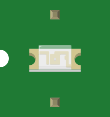
 Design with LEDs in Cirkit Designer
Introduction
Light Emitting Diodes (LEDs) are semiconductor devices that emit light when an electric current passes through them. They are energy-efficient, compact, and have a long lifespan, making them a popular choice for a wide range of applications. LEDs are commonly used as indicators in electronic devices, in digital displays, and for general-purpose lighting in homes, offices, and vehicles. Their versatility and low power consumption make them an essential component in modern electronics.
Explore Projects Built with LEDs
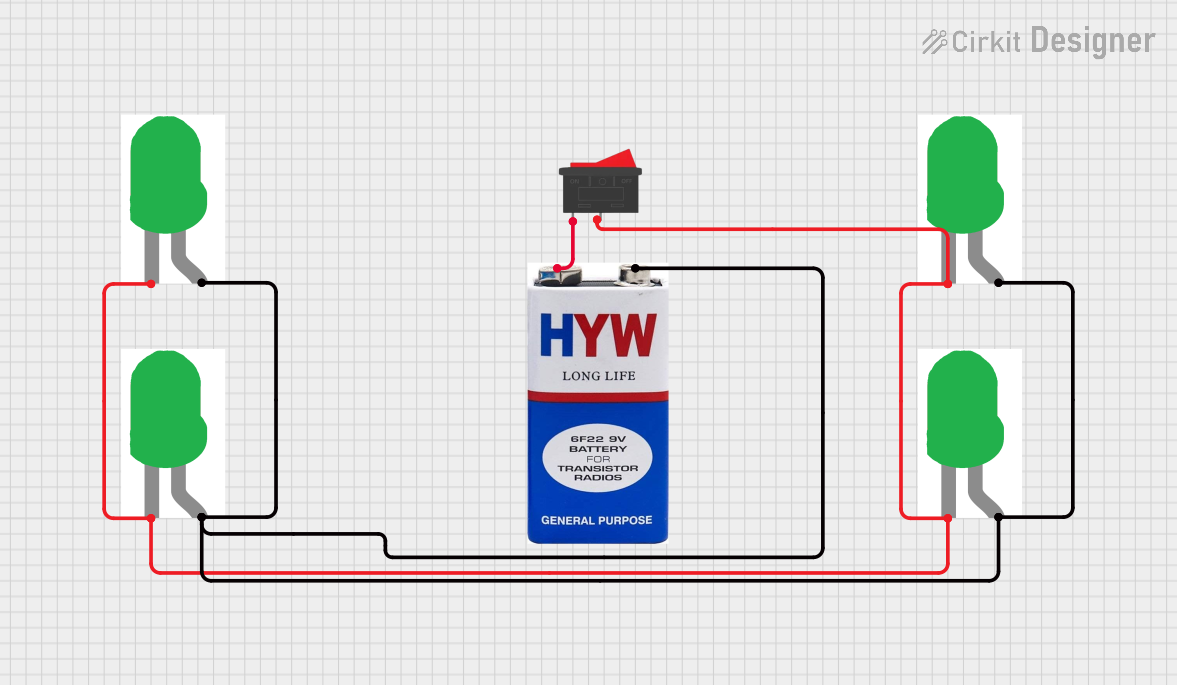 Open Project in Cirkit Designer
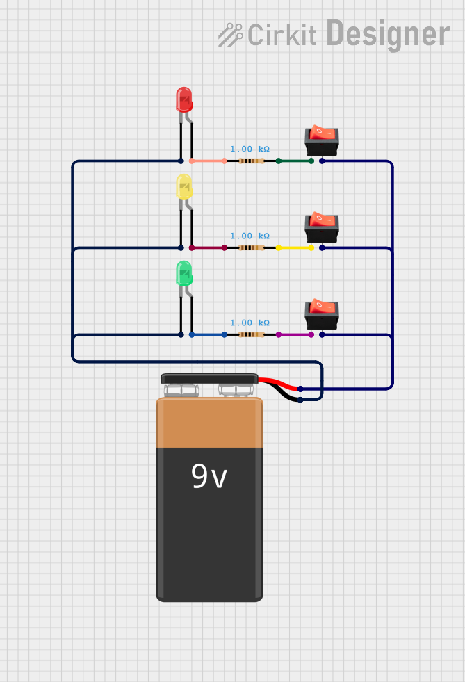 Open Project in Cirkit Designer
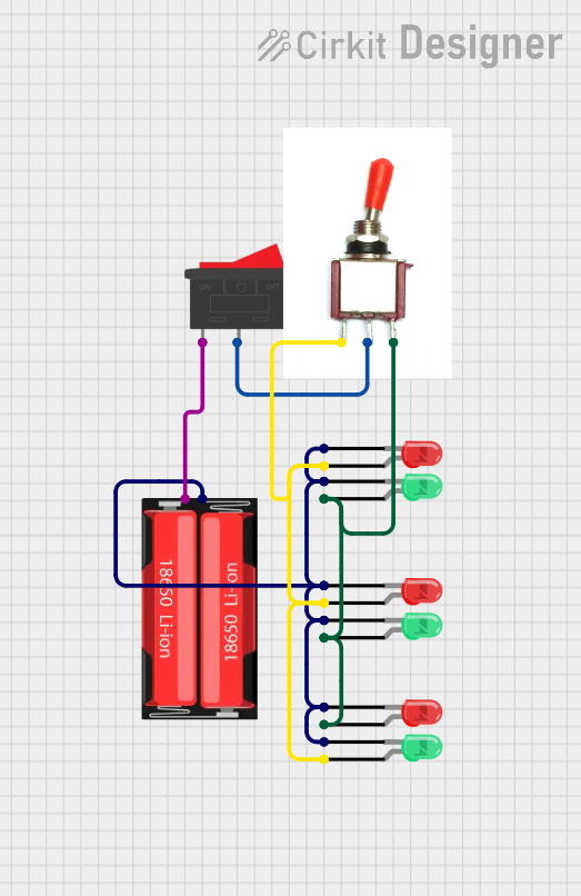 Open Project in Cirkit Designer
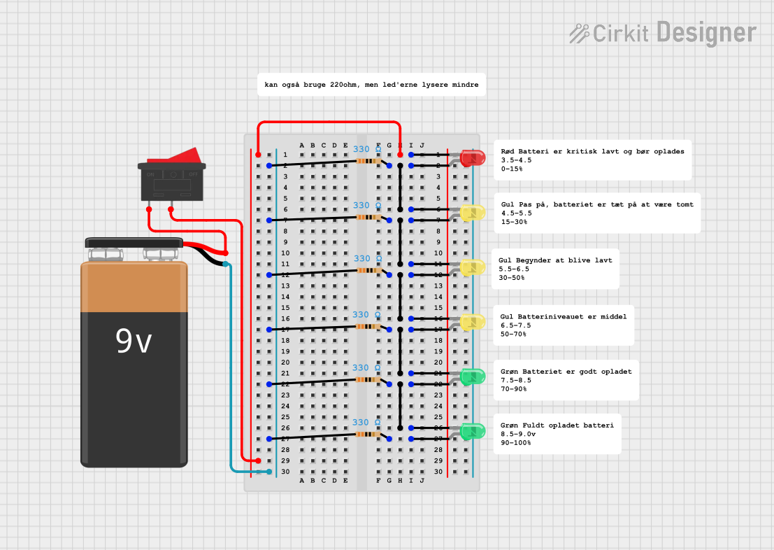 Open Project in Cirkit Designer
Explore Projects Built with LEDs
Open Project in Cirkit DesignerOpen Project in Cirkit DesignerOpen Project in Cirkit DesignerOpen Project in Cirkit DesignerTechnical Specifications
Below are the general technical specifications for standard LEDs. Note that specific values may vary depending on the type and manufacturer.
General Specifications
- Forward Voltage (Vf): 1.8V to 3.3V (varies by color; e.g., red LEDs typically have lower Vf)
- Forward Current (If): 10mA to 30mA (typical operating range)
- Power Dissipation: 30mW to 150mW
- Viewing Angle: 20° to 120° (depends on the LED design)
- Lifespan: 25,000 to 50,000 hours (under optimal conditions)
Pin Configuration and Descriptions
Most standard LEDs have two pins: the anode (positive) and the cathode (negative). The table below describes the pin configuration:
| Pin Name | Description |
|---|---|
| Anode | The longer pin, connected to the positive terminal of the power supply. |
| Cathode | The shorter pin, connected to the negative terminal or ground (GND). |
Color and Forward Voltage Reference
The forward voltage of an LED depends on its color. Below is a reference table:
| LED Color | Forward Voltage (Vf) | Wavelength Range (nm) |
|---|---|---|
| Red | 1.8V - 2.2V | 620 - 750 |
| Green | 2.0V - 3.0V | 495 - 570 |
| Blue | 3.0V - 3.3V | 450 - 495 |
| Yellow | 2.0V - 2.2V | 570 - 590 |
| White | 3.0V - 3.3V | Broad Spectrum |
Usage Instructions
How to Use LEDs in a Circuit
- Determine the Forward Voltage and Current:
- Check the LED's datasheet for its forward voltage (Vf) and forward current (If).
- Choose a Resistor:
- Use a current-limiting resistor to prevent the LED from drawing excessive current. Calculate the resistor value using Ohm's Law:
[
R = \frac{V_{supply} - V_f}{I_f}
]
Where:
- (V_{supply}) is the supply voltage.
- (V_f) is the forward voltage of the LED.
- (I_f) is the desired forward current (in amperes).
- Use a current-limiting resistor to prevent the LED from drawing excessive current. Calculate the resistor value using Ohm's Law:
[
R = \frac{V_{supply} - V_f}{I_f}
]
Where:
- Connect the LED:
- Connect the anode to the positive terminal of the power supply (via the resistor).
- Connect the cathode to the negative terminal or ground (GND).
Example Circuit with Arduino UNO
Below is an example of how to connect and control an LED using an Arduino UNO:
Circuit Setup
- Connect the anode of the LED to a digital pin (e.g., pin 13) on the Arduino through a 220Ω resistor.
- Connect the cathode of the LED to the GND pin on the Arduino.
Arduino Code
// This code blinks an LED connected to pin 13 of the Arduino UNO.
// Ensure the LED is connected with a 220Ω resistor to limit current.

void setup() {
  pinMode(13, OUTPUT); // Set pin 13 as an output pin
}

void loop() {
  digitalWrite(13, HIGH); // Turn the LED on
  delay(1000);            // Wait for 1 second
  digitalWrite(13, LOW);  // Turn the LED off
  delay(1000);            // Wait for 1 second
}
Important Considerations and Best Practices
- Use a Resistor: Always use a current-limiting resistor to protect the LED from excessive current.
- Polarity Matters: Ensure the anode and cathode are connected correctly; reversing the polarity may damage the LED.
- Avoid Overheating: Prolonged exposure to high currents or voltages can reduce the LED's lifespan.
- Check Specifications: Always refer to the LED's datasheet for precise electrical and thermal limits.
Troubleshooting and FAQs
Common Issues and Solutions
LED Does Not Light Up:
- Cause: Incorrect polarity.
- Solution: Ensure the anode is connected to the positive terminal and the cathode to ground.
- Cause: Insufficient current or voltage.
- Solution: Verify the power supply voltage and resistor value.
LED is Dim:
- Cause: Resistor value too high.
- Solution: Recalculate and use a lower resistor value (within safe limits).
LED Burns Out Quickly:
- Cause: Excessive current.
- Solution: Use a proper current-limiting resistor and check the power supply voltage.
Flickering LED:
- Cause: Unstable power supply or loose connections.
- Solution: Ensure stable power and secure all connections.
FAQs
Q: Can I connect an LED directly to a battery?
A: No, always use a current-limiting resistor to prevent damage to the LED.Q: How do I choose the right resistor for my LED?
A: Use the formula (R = \frac{V_{supply} - V_f}{I_f}) to calculate the resistor value.Q: Can I use LEDs with AC power?
A: LEDs are designed for DC power. To use them with AC, you need a rectifier circuit and proper current-limiting components.Q: Why does my LED glow faintly even when off?
A: This could be due to leakage current or a floating pin. Ensure proper grounding and use pull-down resistors if necessary.
By following this documentation, you can effectively use LEDs in your projects while ensuring their longevity and optimal performance.