How to Use MOTOR DRIVER TB12FNG: Examples, Pinouts, and Specs
Introduction
The TB12FNG is a motor driver IC designed to control both DC motors and stepper motors. It is equipped with high current handling capabilities, enabling efficient and reliable motor control. This component is widely used in applications such as robotics, automation systems, and other projects requiring precise motor direction and speed control. Its compact design and versatile functionality make it an excellent choice for hobbyists and professionals alike.
Explore Projects Built with MOTOR DRIVER TB12FNG

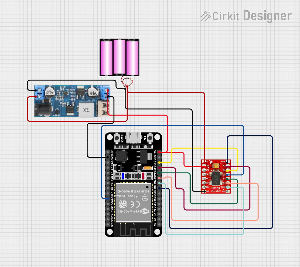
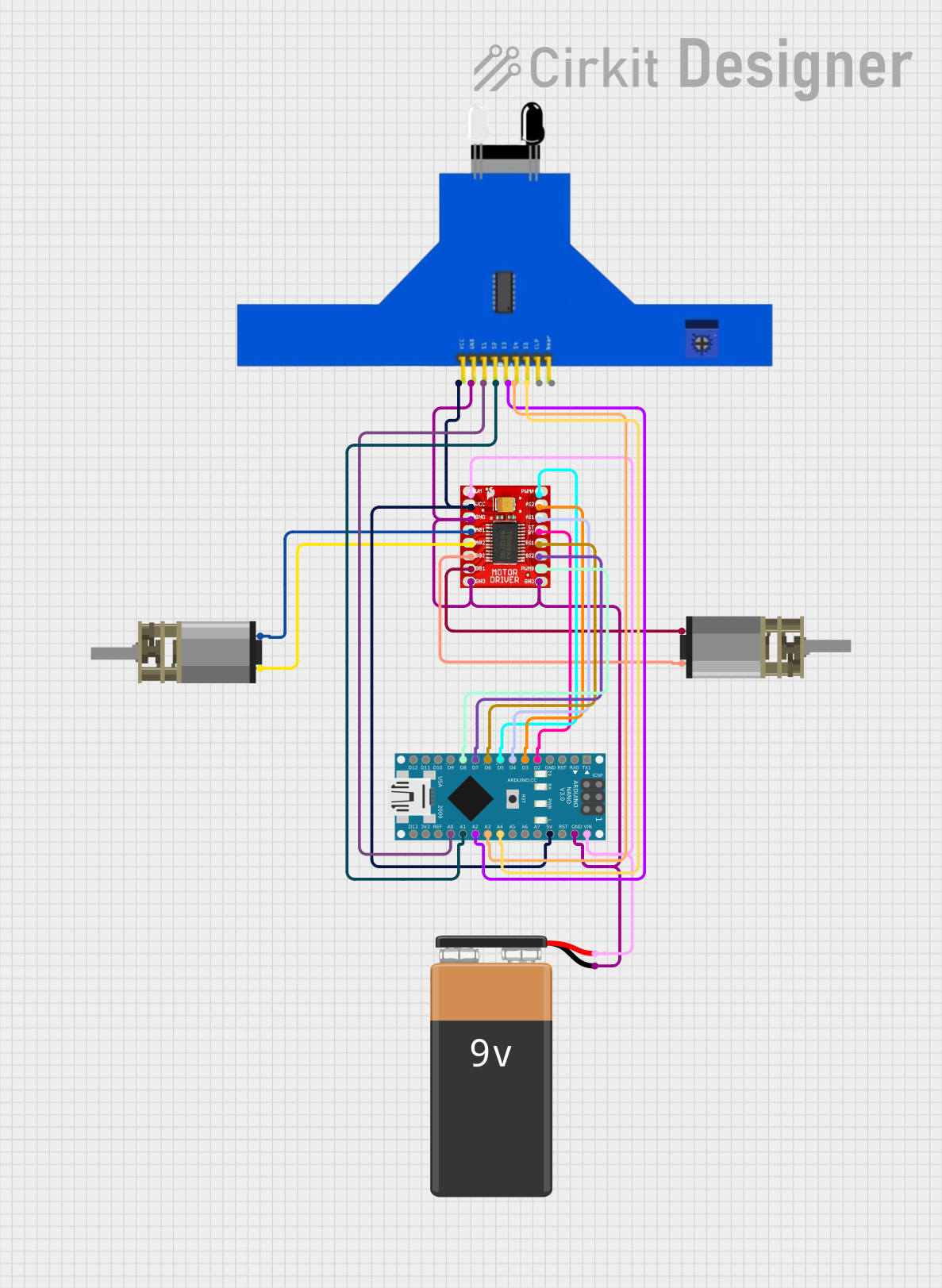
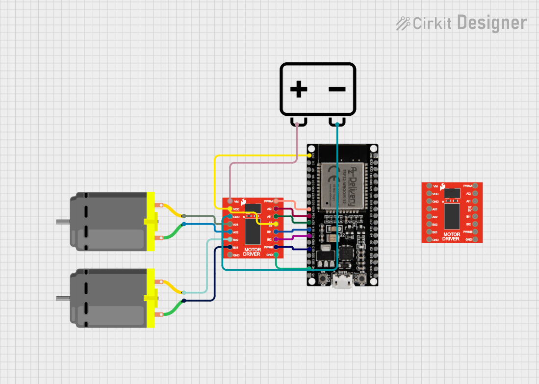
Explore Projects Built with MOTOR DRIVER TB12FNG
Common Applications:
- Robotics for controlling wheels or arms
- Conveyor belt systems in automation
- CNC machines and 3D printers
- Remote-controlled vehicles
- Home appliances requiring motorized components
Technical Specifications
The TB12FNG motor driver IC is designed to handle a wide range of motor control tasks. Below are its key technical details:
Key Specifications:
- Operating Voltage (Vcc): 4.5V to 13.5V
- Output Current (per channel): Up to 1.5A (continuous)
- Peak Output Current: 3A (short duration)
- Control Logic Voltage: 2.7V to 5.5V
- Motor Types Supported: DC motors and stepper motors
- Built-in Protection Features: Overcurrent protection, thermal shutdown, and undervoltage lockout
- Package Type: SSOP24 (compact surface-mount package)
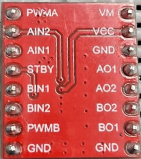
Pin Configuration and Descriptions:
The TB12FNG has 24 pins, each serving a specific function. Below is the pin configuration:
| Pin Number | Pin Name | Description |
|---|---|---|
| 1 | VCC | Power supply for the motor driver (4.5V to 13.5V) |
| 2 | OUT1 | Output for motor winding 1 |
| 3 | OUT2 | Output for motor winding 2 |
| 4 | GND | Ground |
| 5 | IN1 | Input signal to control OUT1 |
| 6 | IN2 | Input signal to control OUT2 |
| 7 | PWM1 | PWM input for speed control of OUT1 |
| 8 | PWM2 | PWM input for speed control of OUT2 |
| 9 | ENABLE | Enable/disable the motor driver |
| 10 | VM | Motor power supply (connect to motor voltage) |
| 11-24 | NC | Not connected |
Usage Instructions
The TB12FNG motor driver is straightforward to use in motor control circuits. Below are the steps and considerations for using this component effectively:
Connecting the TB12FNG:
Power Supply:
- Connect the VCC pin to a regulated power supply (4.5V to 13.5V).
- Connect the VM pin to the motor's power supply voltage.
- Ensure the GND pin is connected to the ground of the circuit.
Motor Connections:
- Connect the motor terminals to OUT1 and OUT2.
- For stepper motors, connect the windings to the appropriate output pins.
Control Inputs:
- Use IN1 and IN2 to control the direction of the motor.
- Apply a PWM signal to PWM1 and PWM2 for speed control.
Enable Pin:
- Set the ENABLE pin high to activate the motor driver.
- Pull the ENABLE pin low to disable the motor driver.
Example Circuit with Arduino UNO:
Below is an example of how to connect and control a DC motor using the TB12FNG and an Arduino UNO:
Circuit Connections:
- TB12FNG Pin | Arduino Pin
- IN1 | Digital Pin 8
- IN2 | Digital Pin 9
- PWM1 | Digital Pin 10 (PWM-capable)
- ENABLE | Digital Pin 7
Arduino Code:
// Example code to control a DC motor using TB12FNG and Arduino UNO

#define IN1 8       // Define IN1 pin
#define IN2 9       // Define IN2 pin
#define PWM1 10     // Define PWM1 pin
#define ENABLE 7    // Define ENABLE pin

void setup() {
  pinMode(IN1, OUTPUT);  // Set IN1 as output
  pinMode(IN2, OUTPUT);  // Set IN2 as output
  pinMode(PWM1, OUTPUT); // Set PWM1 as output
  pinMode(ENABLE, OUTPUT); // Set ENABLE as output

  digitalWrite(ENABLE, HIGH); // Enable the motor driver
}

void loop() {
  // Rotate motor in one direction
  digitalWrite(IN1, HIGH);  // Set IN1 high
  digitalWrite(IN2, LOW);   // Set IN2 low
  analogWrite(PWM1, 128);   // Set motor speed (0-255)

  delay(2000);              // Run for 2 seconds

  // Rotate motor in the opposite direction
  digitalWrite(IN1, LOW);   // Set IN1 low
  digitalWrite(IN2, HIGH);  // Set IN2 high
  analogWrite(PWM1, 128);   // Set motor speed (0-255)

  delay(2000);              // Run for 2 seconds
}
Best Practices:
- Use decoupling capacitors near the VCC and VM pins to reduce noise.
- Ensure the motor's current rating does not exceed the TB12FNG's maximum current capacity.
- Use a heatsink or proper ventilation if operating at high currents for extended periods.
Troubleshooting and FAQs
Common Issues:
Motor Not Spinning:
- Ensure the ENABLE pin is set high.
- Verify the power supply connections to VCC and VM.
- Check the input signals (IN1, IN2, PWM1, PWM2).
Overheating:
- Ensure the motor's current does not exceed the IC's rated capacity.
- Use a heatsink or improve ventilation around the IC.
Erratic Motor Behavior:
- Check for loose connections in the circuit.
- Verify the PWM signal frequency and duty cycle.
FAQs:
Q: Can the TB12FNG drive two DC motors simultaneously?
A: No, the TB12FNG is designed to drive a single DC motor or a single stepper motor.
Q: What is the recommended PWM frequency for speed control?
A: A PWM frequency between 1 kHz and 20 kHz is recommended for optimal performance.
Q: Does the TB12FNG support reverse polarity protection?
A: No, external circuitry is required to protect against reverse polarity.
By following this documentation, users can effectively integrate the TB12FNG motor driver into their projects for precise and reliable motor control.