How to Use RELAY SRD-05VDC-SL-C: Examples, Pinouts, and Specs
Introduction
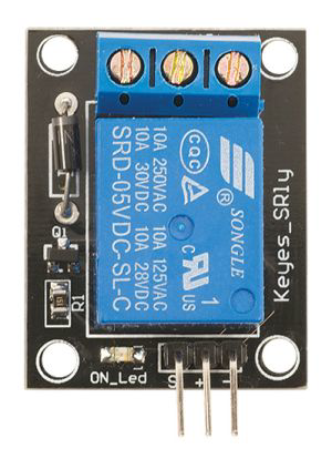
The SRD-05VDC-SL-C is a 5V DC relay module manufactured by SONGLE. It is designed to enable low voltage control signals to switch high voltage devices, making it an essential component in automation, home appliances, and IoT projects. This relay features a Single Pole Double Throw (SPDT) configuration, allowing it to control two circuits (normally open and normally closed) with a single input signal.
Explore Projects Built with RELAY SRD-05VDC-SL-C


Explore Projects Built with RELAY SRD-05VDC-SL-C
Common Applications
- Home automation systems (e.g., controlling lights, fans, or appliances)
- Industrial control systems
- IoT projects for remote device control
- Motor control and switching
- Safety systems and alarms
Technical Specifications
The SRD-05VDC-SL-C relay is designed for reliable and efficient operation in a variety of applications. Below are its key technical details:
Electrical Specifications
| Parameter | Value |
|---|---|
| Operating Voltage | 5V DC |
| Trigger Voltage | 3.75V DC (minimum) |
| Trigger Current | 70 mA |
| Contact Rating | 10A @ 250V AC / 10A @ 30V DC |
| Contact Configuration | SPDT (Single Pole Double Throw) |
| Coil Resistance | 70 Ω |
| Insulation Resistance | ≥100 MΩ (at 500V DC) |
| Dielectric Strength | 500V AC (coil to contact) |
| Operating Temperature | -40°C to +85°C |
| Mechanical Life | 10 million operations |
| Electrical Life | 100,000 operations |
Pin Configuration
The SRD-05VDC-SL-C relay has 5 pins, as described in the table below:
| Pin Number | Pin Name | Description |
|---|---|---|
| 1 | Coil+ (VCC) | Positive terminal of the relay coil. Connect to 5V DC. |
| 2 | Coil- (GND) | Negative terminal of the relay coil. Connect to ground. |
| 3 | Common (COM) | Common terminal for the load circuit. |
| 4 | Normally Open (NO) | Open circuit when the relay is inactive; closed when the relay is activated. |
| 5 | Normally Closed (NC) | Closed circuit when the relay is inactive; open when the relay is activated. |
Usage Instructions
The SRD-05VDC-SL-C relay is straightforward to use in a variety of circuits. Below are the steps and best practices for integrating it into your project:
How to Use the Relay in a Circuit
- Power the Relay Coil: Connect the
Coil+pin to a 5V DC power source and theCoil-pin to ground. This powers the relay's internal coil. - Control the Relay: Use a microcontroller (e.g., Arduino UNO) or a transistor to control the relay. Apply a control signal (≥3.75V DC) to activate the relay.
- Connect the Load:
- Connect the load's power source to the
COMpin. - For a normally open configuration, connect the load to the
NOpin. The circuit will close when the relay is activated. - For a normally closed configuration, connect the load to the
NCpin. The circuit will open when the relay is activated.
- Connect the load's power source to the
Important Considerations
- Flyback Diode: Always use a flyback diode across the relay coil to protect your circuit from voltage spikes when the relay is deactivated.
- Isolation: Ensure proper electrical isolation between the control circuit and the high voltage load to prevent damage or hazards.
- Current Rating: Do not exceed the relay's contact rating (10A @ 250V AC or 10A @ 30V DC) to avoid overheating or failure.
- Mounting: Secure the relay on a PCB or relay module for stable operation.
Example: Using the Relay with an Arduino UNO
Below is an example of how to control the SRD-05VDC-SL-C relay using an Arduino UNO:
Circuit Connections
- Connect the
Coil+pin to a digital output pin on the Arduino (e.g., pin 7). - Connect the
Coil-pin to the Arduino's GND. - Use a 1N4007 diode across the relay coil (anode to
Coil-, cathode toCoil+). - Connect the load to the
COMandNOorNCpins, depending on your desired configuration.
Arduino Code
// Define the relay pin
const int relayPin = 7;

void setup() {
  // Set the relay pin as an output
  pinMode(relayPin, OUTPUT);
}

void loop() {
  // Activate the relay (turn ON the connected device)
  digitalWrite(relayPin, HIGH);
  delay(5000); // Keep the relay ON for 5 seconds

  // Deactivate the relay (turn OFF the connected device)
  digitalWrite(relayPin, LOW);
  delay(5000); // Keep the relay OFF for 5 seconds
}
Troubleshooting and FAQs
Common Issues and Solutions
Relay Not Activating:
- Cause: Insufficient control voltage or current.
- Solution: Ensure the control signal is at least 3.75V DC and the current is ≥70 mA.
Load Not Switching:
- Cause: Incorrect wiring of the load circuit.
- Solution: Verify the connections to the
COM,NO, andNCpins.
Relay Buzzing Noise:
- Cause: Insufficient power supply to the relay coil.
- Solution: Use a stable 5V DC power source with adequate current capacity.
Overheating:
- Cause: Exceeding the relay's contact rating.
- Solution: Ensure the load does not exceed 10A @ 250V AC or 10A @ 30V DC.
FAQs
Q1: Can I use the SRD-05VDC-SL-C relay with a 3.3V microcontroller?
A1: Yes, but you may need a transistor or MOSFET to amplify the control signal to 5V DC.
Q2: Is the relay suitable for switching DC motors?
A2: Yes, but ensure the motor's current and voltage are within the relay's contact rating.
Q3: Can I use the relay for AC loads?
A3: Yes, the relay supports up to 250V AC with a maximum current of 10A.
Q4: Do I need an external flyback diode if I use a relay module?
A4: No, most relay modules include a built-in flyback diode. However, if you're using the standalone relay, you must add one.
By following this documentation, you can effectively integrate the SRD-05VDC-SL-C relay into your projects for reliable and efficient operation.