Cirkit Designer Logo
Cirkit Designer
Your all-in-one circuit design IDE
Home / 
Component Documentation

How to Use mkes0002_ldr_module: Examples, Pinouts, and Specs

Image of mkes0002_ldr_module
Cirkit Designer LogoDesign with mkes0002_ldr_module in Cirkit Designer

Introduction

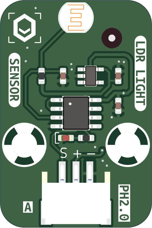
The MKES0002 LDR module, manufactured by MKEVN, is a light-dependent resistor (LDR) sensor module designed to detect ambient light levels. It outputs an analog signal that varies proportionally with the intensity of light falling on the sensor. This module is ideal for applications such as automatic lighting control, light-sensitive alarms, and general-purpose light sensing in electronic projects.

Common applications include:

  • Automatic street lighting systems
  • Light-sensitive alarms
  • Brightness adjustment in displays
  • DIY electronics and Arduino-based projects

Explore Projects Built with mkes0002_ldr_module

Use Cirkit Designer to design, explore, and prototype these projects online. Some projects support real-time simulation. Click "Open Project" to start designing instantly!
Arduino UNO Controlled LDR and LED Circuit
Image of LDR: A project utilizing mkes0002_ldr_module in a practical application
This circuit consists of an Arduino UNO connected to an LDR (Light Dependent Resistor) module and a red LED. The LDR module is powered by the Arduino and its analog output (AO) is connected to the Arduino's analog input (A0) for light intensity measurement. The red LED is connected to a digital output (D13) on the Arduino, with its cathode grounded, allowing the Arduino to control the LED based on the LDR's readings or other logic programmed into the Arduino.
Cirkit Designer LogoOpen Project in Cirkit Designer
Arduino UNO Based LDR-Controlled LED Indicator
Image of switch: A project utilizing mkes0002_ldr_module in a practical application
This circuit features an Arduino UNO connected to an LDR (Light Dependent Resistor) module and an LED with a series resistor. The LDR module is powered by the Arduino's 5V output and its digital output (DO) is connected to the Arduino's analog input A0, potentially for light level sensing. The LED is connected to digital pin D13 through a 220 Ohm resistor, which could be used to indicate the status or the result of the LDR's light sensing.
Cirkit Designer LogoOpen Project in Cirkit Designer
Arduino UNO Light Sensor with LED Indicator
Image of lesson9: A project utilizing mkes0002_ldr_module in a practical application
This circuit uses an Arduino UNO to read data from a Light Dependent Resistor (LDR) module and control a red LED. The LDR is powered by the Arduino and its analog output is connected to the Arduino's A2 pin, while the LED is connected to digital pin D3 through a 200-ohm resistor.
Cirkit Designer LogoOpen Project in Cirkit Designer
Arduino UNO Bluetooth-Controlled Servo with LDR Feedback
Image of gogo: A project utilizing mkes0002_ldr_module in a practical application
This circuit features an Arduino UNO microcontroller interfaced with a Bluetooth HC-06 module for wireless communication, a Tower Pro SG90 servo motor for actuation, and a Module LDR for light intensity sensing. The Arduino controls the servo based on the data received from the LDR or Bluetooth module. The Bluetooth module enables remote control or data exchange, while the LDR provides environmental feedback to the Arduino.
Cirkit Designer LogoOpen Project in Cirkit Designer

Explore Projects Built with mkes0002_ldr_module

Use Cirkit Designer to design, explore, and prototype these projects online. Some projects support real-time simulation. Click "Open Project" to start designing instantly!
Image of LDR: A project utilizing mkes0002_ldr_module in a practical application
Arduino UNO Controlled LDR and LED Circuit
This circuit consists of an Arduino UNO connected to an LDR (Light Dependent Resistor) module and a red LED. The LDR module is powered by the Arduino and its analog output (AO) is connected to the Arduino's analog input (A0) for light intensity measurement. The red LED is connected to a digital output (D13) on the Arduino, with its cathode grounded, allowing the Arduino to control the LED based on the LDR's readings or other logic programmed into the Arduino.
Cirkit Designer LogoOpen Project in Cirkit Designer
Image of switch: A project utilizing mkes0002_ldr_module in a practical application
Arduino UNO Based LDR-Controlled LED Indicator
This circuit features an Arduino UNO connected to an LDR (Light Dependent Resistor) module and an LED with a series resistor. The LDR module is powered by the Arduino's 5V output and its digital output (DO) is connected to the Arduino's analog input A0, potentially for light level sensing. The LED is connected to digital pin D13 through a 220 Ohm resistor, which could be used to indicate the status or the result of the LDR's light sensing.
Cirkit Designer LogoOpen Project in Cirkit Designer
Image of lesson9: A project utilizing mkes0002_ldr_module in a practical application
Arduino UNO Light Sensor with LED Indicator
This circuit uses an Arduino UNO to read data from a Light Dependent Resistor (LDR) module and control a red LED. The LDR is powered by the Arduino and its analog output is connected to the Arduino's A2 pin, while the LED is connected to digital pin D3 through a 200-ohm resistor.
Cirkit Designer LogoOpen Project in Cirkit Designer
Image of gogo: A project utilizing mkes0002_ldr_module in a practical application
Arduino UNO Bluetooth-Controlled Servo with LDR Feedback
This circuit features an Arduino UNO microcontroller interfaced with a Bluetooth HC-06 module for wireless communication, a Tower Pro SG90 servo motor for actuation, and a Module LDR for light intensity sensing. The Arduino controls the servo based on the data received from the LDR or Bluetooth module. The Bluetooth module enables remote control or data exchange, while the LDR provides environmental feedback to the Arduino.
Cirkit Designer LogoOpen Project in Cirkit Designer

Technical Specifications

The MKES0002 LDR module is designed for ease of use and integration into various circuits. Below are its key technical details:

Key Specifications

Parameter Value
Manufacturer MKEVN
Part ID MKES0002
Operating Voltage 3.3V - 5V
Output Type Analog
Light Sensitivity Range 10 lux to 10,000 lux
Dimensions 30mm x 15mm x 10mm
Operating Temperature -20°C to 70°C

Pin Configuration

The MKES0002 LDR module has a simple 3-pin interface for easy connection to microcontrollers and other circuits. The pin configuration is as follows:

Pin Number Pin Name Description
1 VCC Power supply input (3.3V to 5V)
2 GND Ground connection
3 OUT Analog output signal proportional to light level

Usage Instructions

The MKES0002 LDR module is straightforward to use in a circuit. Follow the steps below to integrate it into your project:

Connecting the Module

  1. Power Supply: Connect the VCC pin to a 3.3V or 5V power source and the GND pin to the ground of your circuit.
  2. Output Signal: Connect the OUT pin to an analog input pin of your microcontroller or to an analog-to-digital converter (ADC) if required.

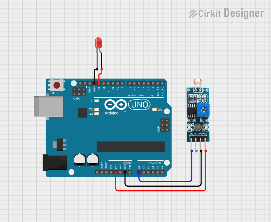
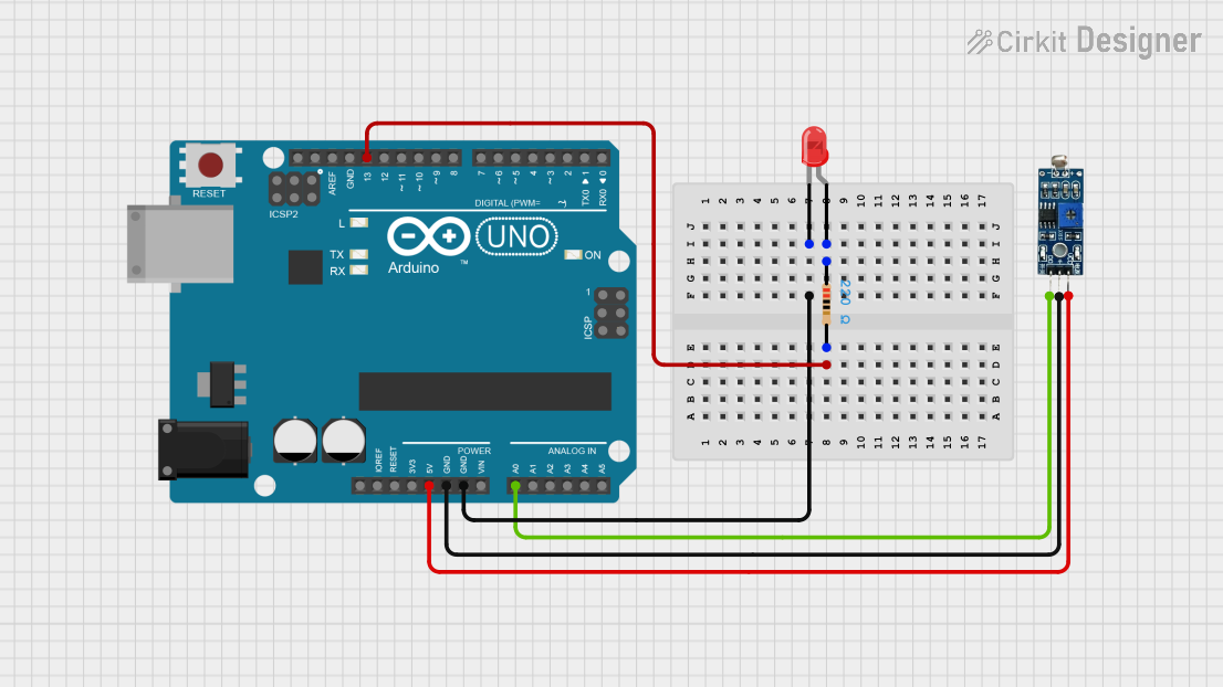
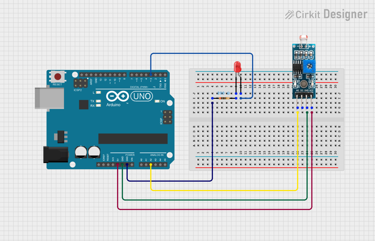
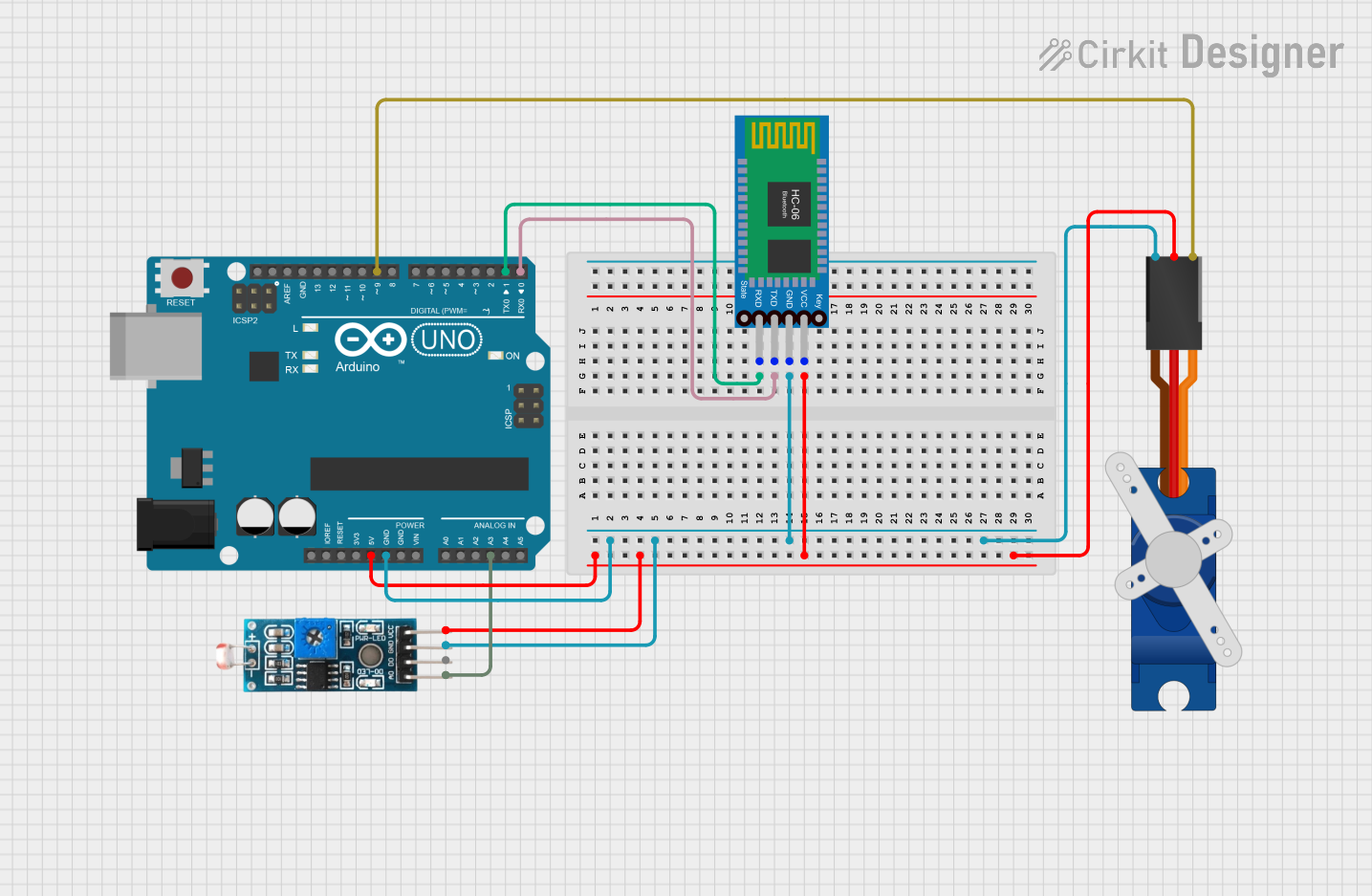
Example Circuit with Arduino UNO

Below is an example of how to connect the MKES0002 LDR module to an Arduino UNO:

  • Connections:
    • VCC → 5V on Arduino
    • GND → GND on Arduino
    • OUT → A0 (Analog Pin 0) on Arduino

Sample Arduino Code

The following Arduino code reads the analog signal from the MKES0002 LDR module and prints the light intensity value to the Serial Monitor:

// Define the analog pin connected to the LDR module
const int ldrPin = A0;

void setup() {
  // Initialize the Serial Monitor for debugging
  Serial.begin(9600);
}

void loop() {
  // Read the analog value from the LDR module
  int lightLevel = analogRead(ldrPin);

  // Convert the analog value to a voltage (assuming 5V reference)
  float voltage = lightLevel * (5.0 / 1023.0);

  // Print the light level and voltage to the Serial Monitor
  Serial.print("Light Level (Raw): ");
  Serial.print(lightLevel);
  Serial.print(" | Voltage: ");
  Serial.print(voltage);
  Serial.println(" V");

  // Add a short delay for readability
  delay(500);
}

Important Considerations

  • Power Supply: Ensure the module is powered within its operating voltage range (3.3V to 5V). Exceeding this range may damage the module.
  • Analog Signal: The OUT pin provides an analog signal that varies with light intensity. Use an ADC or an analog input pin to read this signal.
  • Placement: Place the module in an area where it can accurately sense ambient light without obstructions.

Troubleshooting and FAQs

Common Issues and Solutions

  1. No Output Signal:

    • Cause: Incorrect wiring or insufficient power supply.
    • Solution: Double-check the connections and ensure the module is powered with 3.3V to 5V.
  2. Inconsistent Readings:

    • Cause: Electrical noise or unstable power supply.
    • Solution: Use decoupling capacitors (e.g., 0.1µF) near the power pins to stabilize the supply voltage.
  3. Low Sensitivity:

    • Cause: The module is placed in a poorly lit or obstructed area.
    • Solution: Ensure the module is exposed to the light source without obstructions.
  4. Output Signal Stuck at Maximum or Minimum:

    • Cause: The light intensity is outside the module's sensitivity range.
    • Solution: Verify that the light levels are within the module's specified range (10 lux to 10,000 lux).

FAQs

Q1: Can the MKES0002 LDR module be used outdoors?
A1: Yes, but it should be protected from moisture and extreme environmental conditions. Use an enclosure if necessary.

Q2: How do I increase the sensitivity of the module?
A2: The sensitivity is determined by the LDR and the circuit design. You can adjust the sensitivity by using an external resistor in a voltage divider configuration with the LDR.

Q3: Can I use this module with a 3.3V microcontroller?
A3: Yes, the module operates within a voltage range of 3.3V to 5V, making it compatible with 3.3V microcontrollers like the ESP32.

Q4: What is the maximum distance between the module and the microcontroller?
A4: The distance depends on the quality of the wiring and the environment. For analog signals, keep the distance as short as possible to avoid signal degradation.

By following this documentation, you can effectively integrate the MKES0002 LDR module into your projects and troubleshoot any issues that arise.