
How to Use Directional Switch: Examples, Pinouts, and Specs
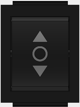
 Design with Directional Switch in Cirkit Designer
Introduction
A directional switch is a device used to control the flow of electrical current in a specific direction, allowing for the selection of different circuit paths. It is commonly used in applications where the control of current flow is critical, such as in motor control, robotics, and power distribution systems. Directional switches are essential in circuits that require switching between multiple outputs or reversing the direction of current flow.
Explore Projects Built with Directional Switch
 Open Project in Cirkit Designer
 Open Project in Cirkit Designer
 Open Project in Cirkit Designer
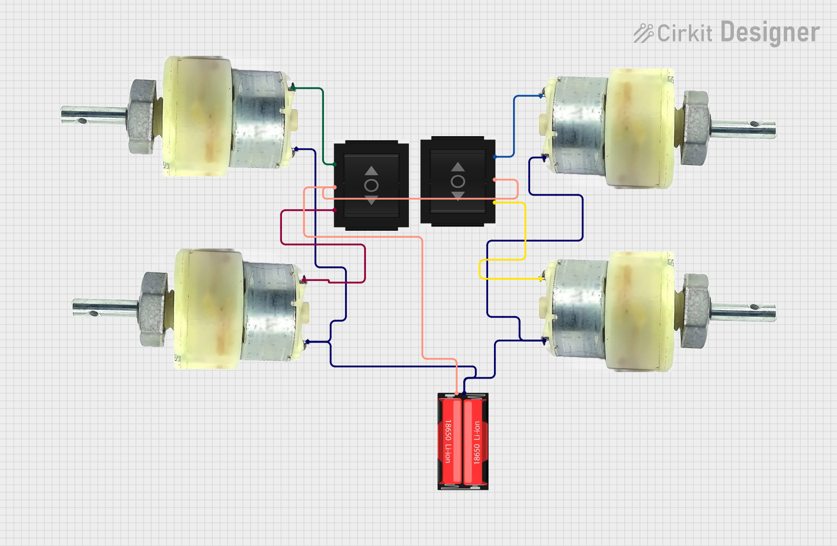 Open Project in Cirkit Designer
Explore Projects Built with Directional Switch
Open Project in Cirkit DesignerOpen Project in Cirkit DesignerOpen Project in Cirkit DesignerOpen Project in Cirkit DesignerCommon Applications and Use Cases
- Motor direction control (e.g., forward/reverse switching)
- Robotics for controlling actuators or motors
- Power distribution systems for selecting different circuit paths
- Audio systems for switching between input/output channels
- Industrial machinery for controlling operational modes
Technical Specifications
Below are the general technical specifications for a typical directional switch. Note that specific models may vary, so always refer to the manufacturer's datasheet for precise details.
Key Technical Details
- Operating Voltage: 3V to 24V DC (varies by model)
- Maximum Current Rating: 5A to 20A (depending on the switch type)
- Contact Resistance: ≤ 50 mΩ
- Insulation Resistance: ≥ 100 MΩ at 500V DC
- Switching Mechanism: Mechanical or electronic
- Number of Positions: 2 to 4 positions (e.g., ON-ON, ON-OFF-ON)
- Operating Temperature Range: -20°C to +85°C
Pin Configuration and Descriptions
Directional switches typically have multiple terminals or pins, depending on the type and number of positions. Below is an example of a 3-pin directional switch configuration:
| Pin Number | Label | Description |
|---|---|---|
| 1 | Common (COM) | The common terminal where the input current is connected. |
| 2 | Output 1 (OUT1) | The terminal connected to the first output path when the switch is in position 1. |
| 3 | Output 2 (OUT2) | The terminal connected to the second output path when the switch is in position 2. |
For a 4-pin directional switch, additional pins may be used for more complex configurations, such as dual-pole switching.
Usage Instructions
How to Use the Component in a Circuit
- Identify the Pins: Refer to the pin configuration table above to identify the common (COM) pin and the output pins (e.g., OUT1, OUT2).
- Connect the Input: Connect the power source or signal to the common (COM) pin.
- Connect the Outputs: Connect the devices or circuit paths to the output pins (e.g., OUT1 and OUT2).
- Switch Operation: Toggle the switch to select the desired output path. For example:
- In position 1, current flows from COM to OUT1.
- In position 2, current flows from COM to OUT2.
Important Considerations and Best Practices
- Current Rating: Ensure the switch can handle the maximum current in your circuit to avoid overheating or damage.
- Voltage Rating: Verify that the operating voltage is within the switch's specified range.
- Debouncing: For mechanical switches, consider using a debouncing circuit or software to eliminate noise caused by rapid switching.
- Mounting: Secure the switch properly to prevent accidental toggling or disconnection.
- Polarity: If used in DC circuits, ensure correct polarity to avoid circuit malfunction.
Example: Using a Directional Switch with Arduino UNO
Below is an example of how to use a directional switch to control the direction of a DC motor using an Arduino UNO.
Circuit Connections
- Connect the common (COM) pin of the switch to the motor's power supply.
- Connect OUT1 and OUT2 to the motor terminals.
- Use the Arduino to monitor the switch state and control the motor.
Arduino Code
// Define pins for the directional switch
const int switchPin1 = 2; // Pin connected to OUT1
const int switchPin2 = 3; // Pin connected to OUT2
const int motorPin = 9;   // PWM pin connected to motor driver

void setup() {
  pinMode(switchPin1, INPUT_PULLUP); // Set switchPin1 as input with pull-up resistor
  pinMode(switchPin2, INPUT_PULLUP); // Set switchPin2 as input with pull-up resistor
  pinMode(motorPin, OUTPUT);         // Set motorPin as output
  Serial.begin(9600);                // Initialize serial communication
}

void loop() {
  // Read the state of the directional switch
  bool switchState1 = digitalRead(switchPin1);
  bool switchState2 = digitalRead(switchPin2);

  if (!switchState1) {
    // Switch is in position 1, rotate motor forward
    analogWrite(motorPin, 255); // Full speed forward
    Serial.println("Motor running forward");
  } else if (!switchState2) {
    // Switch is in position 2, rotate motor backward
    analogWrite(motorPin, 128); // Half speed backward
    Serial.println("Motor running backward");
  } else {
    // Switch is in neutral position, stop motor
    analogWrite(motorPin, 0); // Stop motor
    Serial.println("Motor stopped");
  }

  delay(100); // Small delay for stability
}
Troubleshooting and FAQs
Common Issues Users Might Face
Switch Not Working:
- Cause: Loose connections or incorrect wiring.
- Solution: Double-check all connections and ensure the switch is wired correctly.
Overheating:
- Cause: Exceeding the current or voltage rating of the switch.
- Solution: Use a switch with a higher current/voltage rating or reduce the load.
Noise or Flickering:
- Cause: Mechanical switch bounce.
- Solution: Add a debouncing circuit (e.g., capacitor) or implement software debouncing.
Motor Not Responding:
- Cause: Incorrect Arduino code or wiring.
- Solution: Verify the code logic and ensure proper connections between the switch, motor, and Arduino.
FAQs
Q1: Can I use a directional switch for AC circuits?
A1: Yes, but ensure the switch is rated for AC voltage and current. Some switches are designed specifically for DC or AC applications.
Q2: How do I know the switch position?
A2: Most directional switches have a physical indicator (e.g., lever or toggle) to show the current position.
Q3: Can I use a directional switch to control multiple devices?
A3: Yes, as long as the total current and voltage do not exceed the switch's ratings.
Q4: What is the difference between a directional switch and a DPDT switch?
A4: A directional switch typically controls current flow in one direction at a time, while a DPDT (Double Pole Double Throw) switch can control two independent circuits simultaneously.