How to Use Arduino Micro Pro: Examples, Pinouts, and Specs
Introduction
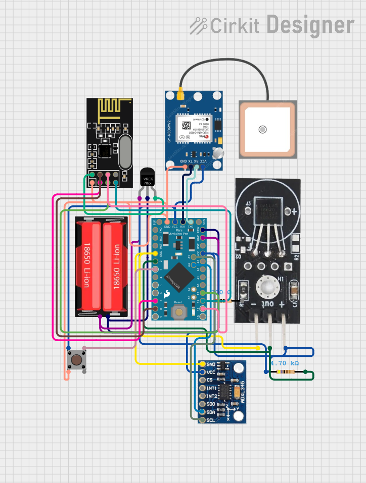
The Arduino Micro Pro is a compact and versatile microcontroller board designed by Arduino, based on the ATmega32U4 microcontroller. It features built-in USB connectivity, making it ideal for projects requiring direct communication with a computer. With its small form factor, the Arduino Micro Pro is perfect for embedded systems, wearable devices, and other space-constrained applications.
Explore Projects Built with Arduino Micro Pro
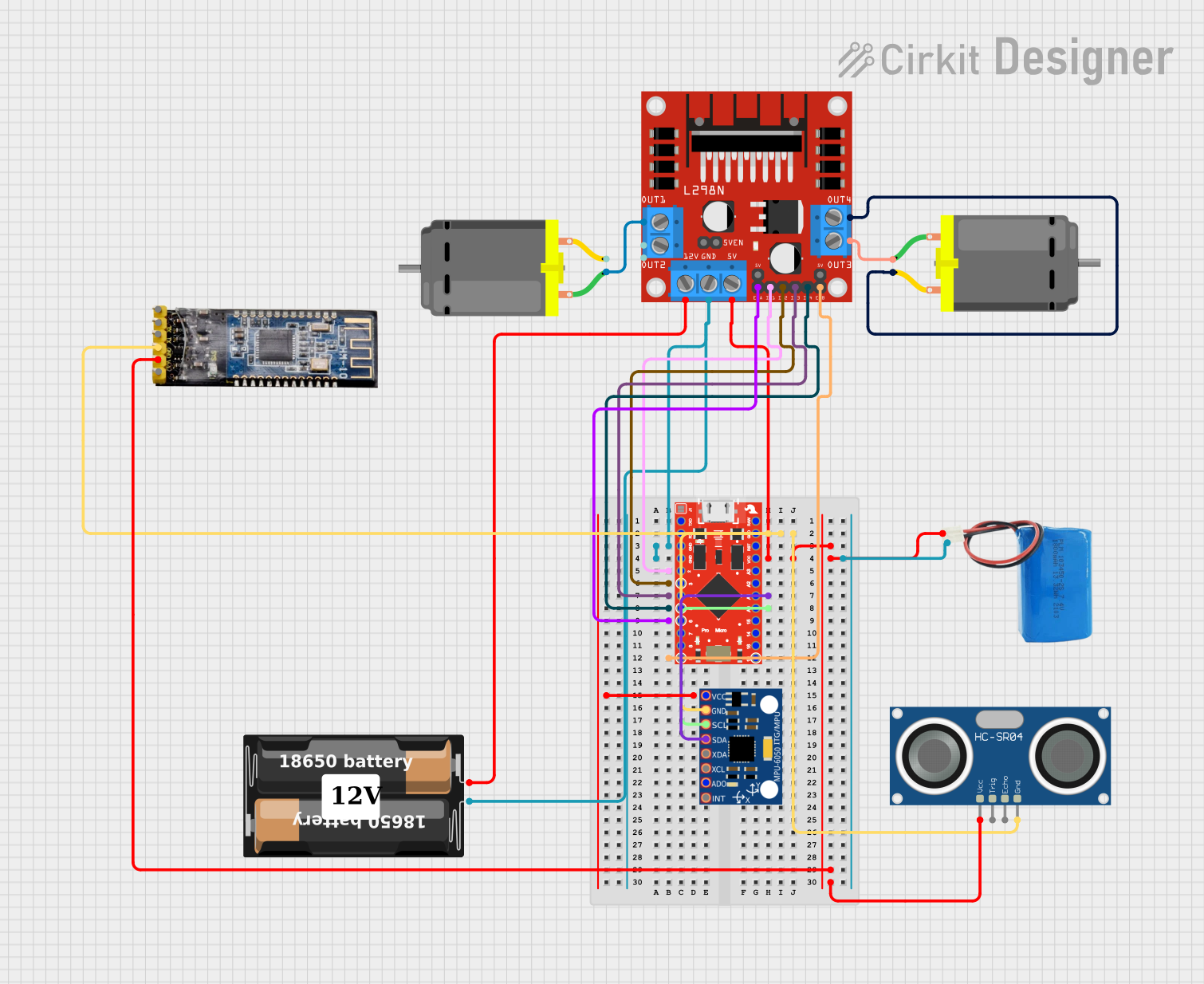
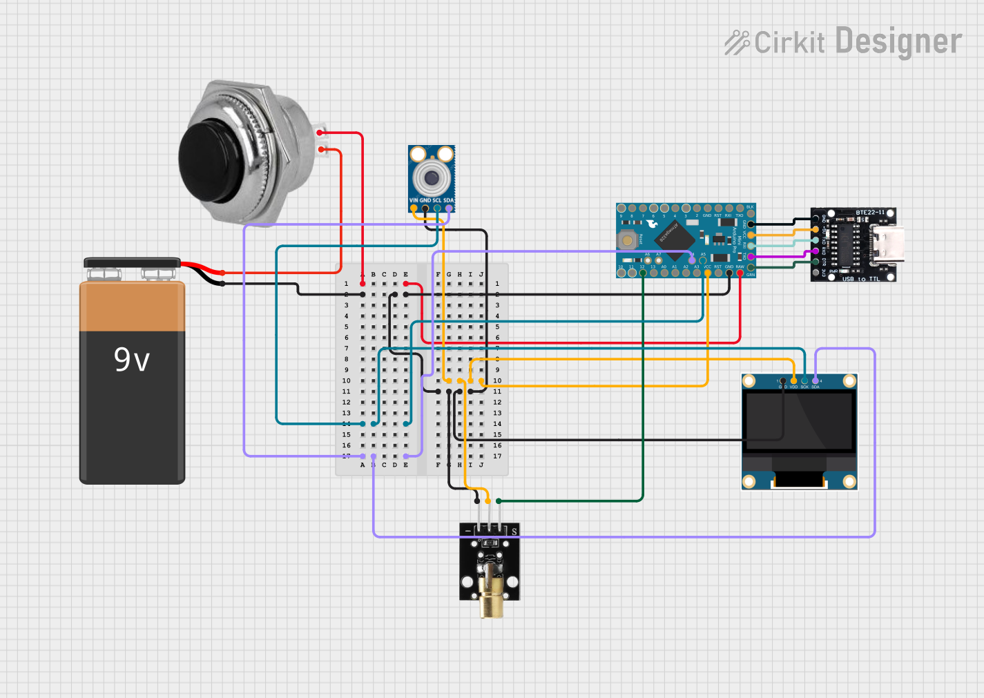
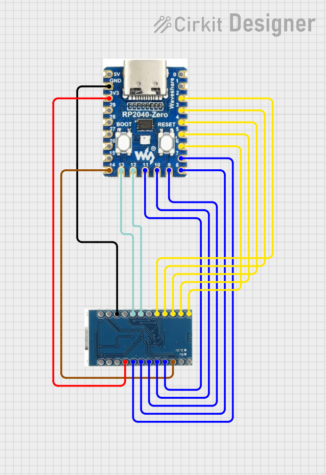
Explore Projects Built with Arduino Micro Pro
Common Applications and Use Cases
- USB-based projects such as keyboards, mice, and game controllers
- Wearable electronics and IoT devices
- Robotics and automation systems
- Prototyping for small-scale embedded systems
- Sensor integration and data logging
Technical Specifications
The following table outlines the key technical details of the Arduino Micro Pro:
| Specification | Details |
|---|---|
| Microcontroller | ATmega32U4 |
| Operating Voltage | 5V |
| Input Voltage (recommended) | 7-12V |
| Input Voltage (limit) | 6-20V |
| Digital I/O Pins | 20 (7 PWM outputs) |
| Analog Input Pins | 12 |
| DC Current per I/O Pin | 20 mA |
| Flash Memory | 32 KB (4 KB used by bootloader) |
| SRAM | 2.5 KB |
| EEPROM | 1 KB |
| Clock Speed | 16 MHz |
| USB Connectivity | Native USB |
| Dimensions | 33 mm x 18 mm |
Pin Configuration and Descriptions
The Arduino Micro Pro has 24 pins, including power, digital I/O, and analog input pins. Below is a detailed pinout description:
| Pin | Type | Description |
|---|---|---|
| VIN | Power Input | Input voltage to the board when using an external power source (7-12V recommended). |
| GND | Ground | Ground connection. |
| 5V | Power Output | Regulated 5V output from the board. |
| RAW | Power Input | Unregulated input voltage (6-20V). |
| A0-A11 | Analog Input | 12 analog input pins (10-bit resolution). |
| D0-D13 | Digital I/O | 14 digital pins, 7 of which support PWM output. |
| TX/RX | Serial I/O | UART communication pins (TX = transmit, RX = receive). |
| SDA | I2C Data | Data line for I2C communication. |
| SCL | I2C Clock | Clock line for I2C communication. |
| RST | Reset | Resets the microcontroller. |
Usage Instructions
How to Use the Arduino Micro Pro in a Circuit
Powering the Board:
- Connect the board to your computer via a USB cable for power and programming.
- Alternatively, supply power through the VIN pin (7-12V recommended) or the RAW pin (6-20V).
Programming the Board:
- Open the Arduino IDE on your computer.
- Select Arduino Leonardo as the board type (since the Micro Pro uses the same ATmega32U4 microcontroller).
- Connect the board via USB and select the appropriate COM port.
- Write your code and upload it to the board.
Connecting Components:
- Use the digital I/O pins for controlling LEDs, relays, or other digital devices.
- Use the analog input pins to read sensor data (e.g., temperature, light, or potentiometers).
- For communication, use the UART (TX/RX), I2C (SDA/SCL), or SPI pins.
Important Considerations and Best Practices
- Avoid exceeding the maximum current rating of 20 mA per I/O pin to prevent damage.
- Use pull-up or pull-down resistors for stable digital input readings.
- When using the board in USB HID (Human Interface Device) mode, ensure proper USB driver installation.
- For power-hungry peripherals, consider using an external power source instead of USB power.
Example Code: Blinking an LED
The following example demonstrates how to blink an LED connected to pin 13 of the Arduino Micro Pro:
// This example code blinks an LED connected to pin 13 of the Arduino Micro Pro.
// The LED will turn on for 1 second and off for 1 second in a loop.

void setup() {
  pinMode(13, OUTPUT); // Set pin 13 as an output pin
}

void loop() {
  digitalWrite(13, HIGH); // Turn the LED on
  delay(1000);            // Wait for 1 second
  digitalWrite(13, LOW);  // Turn the LED off
  delay(1000);            // Wait for 1 second
}
Example Code: Reading an Analog Sensor
The following example reads data from a sensor connected to analog pin A0 and prints the value to the Serial Monitor:
// This example reads an analog value from pin A0 and prints it to the Serial Monitor.

void setup() {
  Serial.begin(9600); // Initialize serial communication at 9600 baud
}

void loop() {
  int sensorValue = analogRead(A0); // Read the analog value from pin A0
  Serial.println(sensorValue);      // Print the value to the Serial Monitor
  delay(500);                       // Wait for 500 milliseconds
}
Troubleshooting and FAQs
Common Issues and Solutions
The board is not recognized by the computer:
- Ensure the USB cable is functional and supports data transfer.
- Check that the correct drivers are installed for the Arduino Micro Pro.
Unable to upload code to the board:
- Verify that the correct board type (Arduino Leonardo) is selected in the Arduino IDE.
- Ensure the correct COM port is selected.
- Press the reset button on the board before uploading the code.
The board is not powering on:
- Check the power source and ensure it meets the voltage requirements.
- Inspect the USB cable or external power connections for faults.
Erratic behavior or unexpected resets:
- Ensure the power supply is stable and not fluctuating.
- Avoid drawing excessive current from the I/O pins.
FAQs
Q: Can the Arduino Micro Pro act as a USB keyboard or mouse?
A: Yes, the ATmega32U4 microcontroller supports USB HID functionality, allowing the board to emulate a keyboard, mouse, or other USB devices.
Q: What is the difference between the Arduino Micro Pro and the Arduino Leonardo?
A: Both boards use the ATmega32U4 microcontroller, but the Micro Pro is smaller and more compact, making it suitable for space-constrained projects.
Q: Can I power the board with a 3.7V LiPo battery?
A: No, the recommended input voltage is 7-12V via the VIN pin. For lower voltages, use a step-up converter to meet the required input voltage.
Q: How do I reset the board manually?
A: Press the reset button on the board to restart the microcontroller. This is useful for troubleshooting or entering the bootloader mode.