
How to Use USB_AB: Examples, Pinouts, and Specs
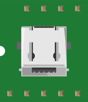
 Design with USB_AB in Cirkit Designer
Introduction
The USB_AB connector is a versatile USB interface that supports both USB-A and USB-B connections. This dual compatibility makes it an ideal choice for devices requiring flexible connectivity options. It is commonly used in applications such as data transfer, charging, and interfacing between computers, peripherals, and embedded systems. Its robust design ensures reliable performance in a wide range of environments.
Explore Projects Built with USB_AB
 Open Project in Cirkit Designer
 Open Project in Cirkit Designer
 Open Project in Cirkit Designer
 Open Project in Cirkit Designer
Explore Projects Built with USB_AB
Open Project in Cirkit DesignerOpen Project in Cirkit DesignerOpen Project in Cirkit DesignerOpen Project in Cirkit DesignerCommon Applications:
- Connecting computers to peripherals (e.g., printers, scanners, external drives)
- Power delivery and charging for devices
- Embedded systems requiring USB communication
- Prototyping and development boards
Technical Specifications
Key Technical Details:
- Connector Type: USB-A and USB-B compatible
- Voltage Rating: 5V DC (standard USB voltage)
- Current Rating: Up to 1.5A (USB 2.0) or 3A (USB 3.0/3.1)
- Data Transfer Rate:
- USB 2.0: Up to 480 Mbps
- USB 3.0/3.1: Up to 5 Gbps
- Operating Temperature: -20°C to 70°C
- Durability: Rated for 1,500 to 5,000 mating cycles
Pin Configuration and Descriptions:
The USB_AB connector has four primary pins for USB 2.0 and additional pins for USB 3.0/3.1 functionality. Below is the pinout for USB 2.0 and USB 3.0/3.1:
USB 2.0 Pinout:
| Pin Number | Name | Description |
|---|---|---|
| 1 | VBUS | +5V Power Supply |
| 2 | D- | Data Line (Negative) |
| 3 | D+ | Data Line (Positive) |
| 4 | GND | Ground |
USB 3.0/3.1 Additional Pins:
| Pin Number | Name | Description |
|---|---|---|
| 5 | StdA_SSRX- | SuperSpeed Receiver (Negative) |
| 6 | StdA_SSRX+ | SuperSpeed Receiver (Positive) |
| 7 | GND_DRAIN | Ground for SuperSpeed Signals |
| 8 | StdA_SSTX- | SuperSpeed Transmitter (Negative) |
| 9 | StdA_SSTX+ | SuperSpeed Transmitter (Positive) |
Usage Instructions
How to Use the USB_AB Connector in a Circuit:
- Identify the Required USB Mode: Determine whether your application requires USB 2.0 or USB 3.0/3.1 functionality.
- Connect the Pins Appropriately:
- For USB 2.0, connect the VBUS, D-, D+, and GND pins to the corresponding lines in your circuit.
- For USB 3.0/3.1, ensure the additional SuperSpeed pins are also connected for high-speed data transfer.
- Power Supply Considerations:
- Ensure the power supply provides a stable 5V DC output.
- Verify that the current rating of the power source matches the requirements of the connected device.
- PCB Design:
- Use proper trace widths for power and ground lines to handle the required current.
- Minimize noise by keeping data lines (D- and D+) as short and parallel as possible.
- Testing:
- Verify the connections with a multimeter before powering the circuit.
- Test data transfer functionality using a compatible USB device.
Example: Connecting USB_AB to an Arduino UNO
The USB_AB connector can be used to interface an Arduino UNO with a computer for programming and serial communication. Below is an example of Arduino code for basic serial communication:
// Arduino Serial Communication Example
// This code sends a message to the serial monitor every second.

void setup() {
  Serial.begin(9600); // Initialize serial communication at 9600 baud
  // Ensure the USB_AB connector is properly connected to the Arduino UNO
  // and the computer for serial communication.
}

void loop() {
  Serial.println("Hello, USB_AB!"); // Send a message to the serial monitor
  delay(1000); // Wait for 1 second before sending the next message
}
Best Practices:
- Use shielded USB cables to minimize electromagnetic interference (EMI).
- Avoid excessive bending or pulling of the USB_AB connector to ensure durability.
- For USB 3.0/3.1 applications, use high-quality cables rated for SuperSpeed data transfer.
Troubleshooting and FAQs
Common Issues and Solutions:
No Power or Device Not Recognized:
- Cause: Loose or incorrect connections.
- Solution: Verify all connections, especially the VBUS and GND pins. Ensure the USB cable is functional.
Slow Data Transfer Speeds:
- Cause: Using a USB 2.0 cable for a USB 3.0/3.1 application.
- Solution: Use a cable rated for USB 3.0/3.1 to achieve higher speeds.
Overheating:
- Cause: Excessive current draw or poor ventilation.
- Solution: Ensure the connected device does not exceed the current rating of the USB_AB connector. Improve ventilation around the circuit.
Intermittent Connection:
- Cause: Worn-out connector or poor soldering.
- Solution: Replace the connector or re-solder the connections.
FAQs:
Q: Can I use the USB_AB connector for charging only?
- A: Yes, the USB_AB connector can be used solely for power delivery by connecting only the VBUS and GND pins.
Q: Is the USB_AB connector backward compatible with USB 1.1?
- A: Yes, the USB_AB connector is backward compatible with USB 1.1, but data transfer speeds will be limited to USB 1.1 standards.
Q: How do I differentiate between USB-A and USB-B connections?
- A: USB-A connectors are typically rectangular and flat, while USB-B connectors are square with a slight bevel on the top corners.
By following this documentation, users can effectively integrate the USB_AB connector into their projects and troubleshoot common issues.