How to Use SS14 Schottky DIODE: Examples, Pinouts, and Specs
Introduction
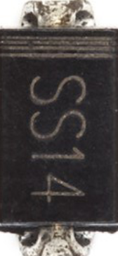
The SS14 is a Schottky diode designed for applications requiring low forward voltage drop and fast switching speed. Its compact design and efficient performance make it ideal for use in power rectification, voltage clamping, and reverse polarity protection. The SS14 is widely used in power supplies, DC-DC converters, and other electronic circuits where efficiency and reliability are critical.
Explore Projects Built with SS14 Schottky DIODE


Explore Projects Built with SS14 Schottky DIODE
Common Applications
- Power rectification in AC-DC and DC-DC converters
- Voltage clamping to protect sensitive components
- Reverse polarity protection in circuits
- Freewheeling diodes in motor control applications
Technical Specifications
Key Specifications
| Parameter | Value |
|---|---|
| Maximum Repetitive Peak Reverse Voltage (VRRM) | 40V |
| Maximum Average Forward Rectified Current (IF(AV)) | 1A |
| Peak Forward Surge Current (IFSM) | 30A (8.3ms single half sine-wave) |
| Forward Voltage Drop (VF) | 0.55V (at 1A) |
| Reverse Current (IR) | 0.5mA (at VR = 40V) |
| Operating Temperature Range | -55°C to +125°C |
| Package Type | DO-214AC (SMA) |
Pin Configuration
The SS14 Schottky diode has two terminals:
| Pin Number | Pin Name | Description |
|---|---|---|
| 1 | Anode | Positive terminal of the diode |
| 2 | Cathode | Negative terminal of the diode |
The cathode is typically marked with a stripe on the diode body for easy identification.
Usage Instructions
How to Use the SS14 in a Circuit
- Determine the Orientation: Identify the cathode (marked with a stripe) and anode. Connect the anode to the positive side of the circuit and the cathode to the negative side.
- Voltage and Current Ratings: Ensure the input voltage does not exceed the maximum reverse voltage (40V) and the current does not exceed the maximum average forward current (1A).
- Heat Dissipation: If the diode operates near its maximum current rating, consider adding a heatsink or ensuring proper ventilation to prevent overheating.
- Soldering: When soldering the SS14, avoid excessive heat to prevent damage to the diode. Use a soldering iron with a temperature below 260°C and limit soldering time to 10 seconds.
Example: Using the SS14 with an Arduino UNO
The SS14 can be used for reverse polarity protection in circuits powered by an Arduino UNO. Below is an example circuit and code to demonstrate its use:
Circuit Description
- Place the SS14 diode between the power source and the Arduino's VIN pin.
- Connect the anode of the SS14 to the positive terminal of the power source.
- Connect the cathode of the SS14 to the VIN pin of the Arduino.
Arduino Code Example
// Example code to blink an LED connected to pin 13 of the Arduino UNO
// This assumes the SS14 diode is used for reverse polarity protection
// in the power supply circuit.

void setup() {
  pinMode(13, OUTPUT); // Set pin 13 as an output
}

void loop() {
  digitalWrite(13, HIGH); // Turn the LED on
  delay(1000);            // Wait for 1 second
  digitalWrite(13, LOW);  // Turn the LED off
  delay(1000);            // Wait for 1 second
}
Best Practices
- Always verify the diode's orientation before powering the circuit.
- Use a fuse in series with the diode for additional protection in high-current applications.
- Avoid exceeding the diode's voltage and current ratings to ensure long-term reliability.
Troubleshooting and FAQs
Common Issues and Solutions
Diode Overheating:
- Cause: Excessive current or insufficient heat dissipation.
- Solution: Reduce the current load or improve cooling (e.g., add a heatsink).
No Voltage Across the Diode:
- Cause: Incorrect orientation of the diode.
- Solution: Verify the anode and cathode connections.
High Reverse Leakage Current:
- Cause: Operating the diode near its maximum reverse voltage.
- Solution: Use a diode with a higher reverse voltage rating if necessary.
Circuit Not Powering On:
- Cause: Faulty diode or improper soldering.
- Solution: Test the diode with a multimeter and re-solder if needed.
FAQs
Q1: Can the SS14 handle AC signals?
A1: The SS14 is primarily designed for rectifying AC signals into DC. However, it cannot block reverse AC voltages exceeding its maximum reverse voltage rating (40V).
Q2: What is the difference between a Schottky diode and a regular diode?
A2: Schottky diodes, like the SS14, have a lower forward voltage drop (typically 0.2V to 0.55V) and faster switching speeds compared to regular silicon diodes. This makes them more efficient in high-frequency and low-voltage applications.
Q3: Can I use the SS14 for high-current applications?
A3: The SS14 is rated for a maximum average forward current of 1A. For higher currents, consider using a diode with a higher current rating.
Q4: How do I test if my SS14 diode is working?
A4: Use a multimeter in diode mode. Connect the positive probe to the anode and the negative probe to the cathode. A forward voltage drop of approximately 0.55V indicates the diode is functioning correctly. Reverse the probes to check for no current flow, confirming proper operation.