Cirkit Designer Logo
Cirkit Designer
Your all-in-one circuit design IDE
Home / 
Component Documentation

How to Use Photoresistor Module: Examples, Pinouts, and Specs

Image of Photoresistor Module
Cirkit Designer LogoDesign with Photoresistor Module in Cirkit Designer

Introduction

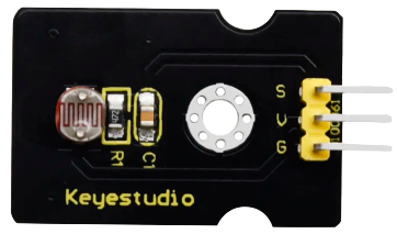
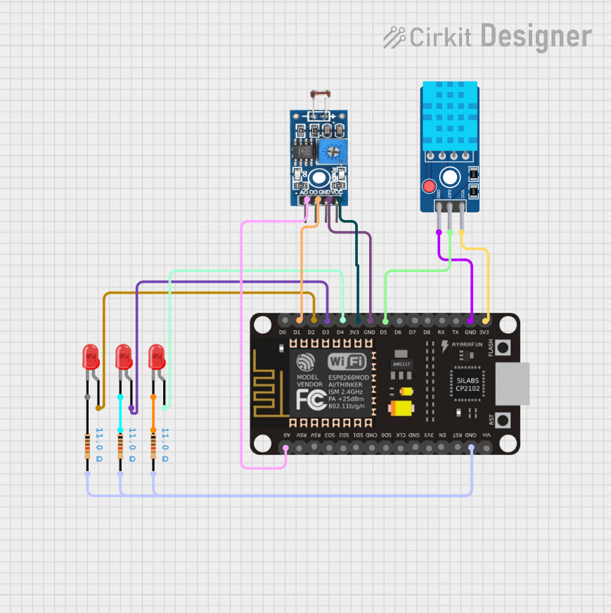
A photoresistor module is a light-sensitive component that changes its resistance based on the intensity of light falling on it. The module typically consists of a photoresistor (also known as an LDR or Light Dependent Resistor) and additional circuitry to make it easier to interface with microcontrollers or other electronic systems.

Explore Projects Built with Photoresistor Module

Use Cirkit Designer to design, explore, and prototype these projects online. Some projects support real-time simulation. Click "Open Project" to start designing instantly!
Arduino UNO Based LDR-Controlled LED Indicator
Image of switch: A project utilizing Photoresistor Module in a practical application
This circuit features an Arduino UNO connected to an LDR (Light Dependent Resistor) module and an LED with a series resistor. The LDR module is powered by the Arduino's 5V output and its digital output (DO) is connected to the Arduino's analog input A0, potentially for light level sensing. The LED is connected to digital pin D13 through a 220 Ohm resistor, which could be used to indicate the status or the result of the LDR's light sensing.
Cirkit Designer LogoOpen Project in Cirkit Designer
Arduino UNO Controlled LDR and LED Circuit
Image of LDR: A project utilizing Photoresistor Module in a practical application
This circuit consists of an Arduino UNO connected to an LDR (Light Dependent Resistor) module and a red LED. The LDR module is powered by the Arduino and its analog output (AO) is connected to the Arduino's analog input (A0) for light intensity measurement. The red LED is connected to a digital output (D13) on the Arduino, with its cathode grounded, allowing the Arduino to control the LED based on the LDR's readings or other logic programmed into the Arduino.
Cirkit Designer LogoOpen Project in Cirkit Designer
Arduino-Controlled Servo with Light Sensing
Image of Servo: A project utilizing Photoresistor Module in a practical application
This circuit features an Arduino UNO microcontroller interfaced with two photocells (LDRs) and a servo motor. The photocells are connected to analog inputs A0 and A1, and their average light intensity reading is used to control the position of the servo motor connected to digital pin D9. The circuit is powered by a pair of 18650 Li-ion batteries, which are also connected to a TP4056 charging module that can be charged via a solar cell, providing a renewable energy source for the system.
Cirkit Designer LogoOpen Project in Cirkit Designer
ESP8266 NodeMCU Controlled Environment Monitoring System with MQTT
Image of iot: A project utilizing Photoresistor Module in a practical application
This circuit features an ESP8266 NodeMCU microcontroller connected to a photosensitive sensor module for light intensity detection, a DHT11 sensor for temperature and humidity readings, and three LEDs with corresponding resistors. The microcontroller reads the analog value from the light sensor, digital signals from the DHT11 sensor, and controls the LEDs based on MQTT messages received over WiFi. The circuit is designed for environmental monitoring and remote control of the LEDs, likely for smart home applications.
Cirkit Designer LogoOpen Project in Cirkit Designer

Explore Projects Built with Photoresistor Module

Use Cirkit Designer to design, explore, and prototype these projects online. Some projects support real-time simulation. Click "Open Project" to start designing instantly!
Image of switch: A project utilizing Photoresistor Module in a practical application
Arduino UNO Based LDR-Controlled LED Indicator
This circuit features an Arduino UNO connected to an LDR (Light Dependent Resistor) module and an LED with a series resistor. The LDR module is powered by the Arduino's 5V output and its digital output (DO) is connected to the Arduino's analog input A0, potentially for light level sensing. The LED is connected to digital pin D13 through a 220 Ohm resistor, which could be used to indicate the status or the result of the LDR's light sensing.
Cirkit Designer LogoOpen Project in Cirkit Designer
Image of LDR: A project utilizing Photoresistor Module in a practical application
Arduino UNO Controlled LDR and LED Circuit
This circuit consists of an Arduino UNO connected to an LDR (Light Dependent Resistor) module and a red LED. The LDR module is powered by the Arduino and its analog output (AO) is connected to the Arduino's analog input (A0) for light intensity measurement. The red LED is connected to a digital output (D13) on the Arduino, with its cathode grounded, allowing the Arduino to control the LED based on the LDR's readings or other logic programmed into the Arduino.
Cirkit Designer LogoOpen Project in Cirkit Designer
Image of Servo: A project utilizing Photoresistor Module in a practical application
Arduino-Controlled Servo with Light Sensing
This circuit features an Arduino UNO microcontroller interfaced with two photocells (LDRs) and a servo motor. The photocells are connected to analog inputs A0 and A1, and their average light intensity reading is used to control the position of the servo motor connected to digital pin D9. The circuit is powered by a pair of 18650 Li-ion batteries, which are also connected to a TP4056 charging module that can be charged via a solar cell, providing a renewable energy source for the system.
Cirkit Designer LogoOpen Project in Cirkit Designer
Image of iot: A project utilizing Photoresistor Module in a practical application
ESP8266 NodeMCU Controlled Environment Monitoring System with MQTT
This circuit features an ESP8266 NodeMCU microcontroller connected to a photosensitive sensor module for light intensity detection, a DHT11 sensor for temperature and humidity readings, and three LEDs with corresponding resistors. The microcontroller reads the analog value from the light sensor, digital signals from the DHT11 sensor, and controls the LEDs based on MQTT messages received over WiFi. The circuit is designed for environmental monitoring and remote control of the LEDs, likely for smart home applications.
Cirkit Designer LogoOpen Project in Cirkit Designer

Common Applications and Use Cases

  • Automatic lighting systems (e.g., streetlights that turn on at night)
  • Light-sensitive alarms and security systems
  • Brightness detection for displays or screens
  • Solar tracking systems
  • DIY electronics projects involving light detection

Technical Specifications

The photoresistor module is designed to provide an analog or digital output based on the light intensity. Below are the key technical details:

Key Technical Details

  • Operating Voltage: 3.3V to 5V DC
  • Output Type: Analog (voltage varies with light intensity) and Digital (threshold-based)
  • Sensitivity Range: 10 lux to 10,000 lux (approximate, depending on the module)
  • Response Time: ~20ms to 30ms
  • Operating Temperature: -30°C to 70°C
  • Dimensions: Varies by module, typically ~30mm x 20mm

Pin Configuration and Descriptions

The photoresistor module typically has three pins. Below is the pinout description:

Pin Name Description
1 VCC Power supply pin. Connect to 3.3V or 5V DC.
2 GND Ground pin. Connect to the ground of the power supply.
3 OUT Output pin. Provides an analog voltage proportional to light intensity or a
digital HIGH/LOW signal depending on the module's configuration.

Note: Some modules may include a potentiometer to adjust the threshold for the digital output.

Usage Instructions

How to Use the Component in a Circuit

  1. Power the Module: Connect the VCC pin to a 3.3V or 5V power source and the GND pin to the ground.
  2. Connect the Output:
    • For analog output, connect the OUT pin to an analog input pin of your microcontroller.
    • For digital output, connect the OUT pin to a digital input pin of your microcontroller.
  3. Adjust Sensitivity (if applicable): If the module has a potentiometer, adjust it to set the light intensity threshold for the digital output.

Important Considerations and Best Practices

  • Avoid Direct Sunlight: Prolonged exposure to direct sunlight may degrade the photoresistor's performance over time.
  • Use Pull-Down Resistors: If using the digital output, consider adding a pull-down resistor to ensure a stable LOW signal when no light is detected.
  • Shield from Electrical Noise: Place the module away from high-frequency components to avoid interference.
  • Calibrate for Accuracy: For precise applications, calibrate the module by testing it under known light conditions.

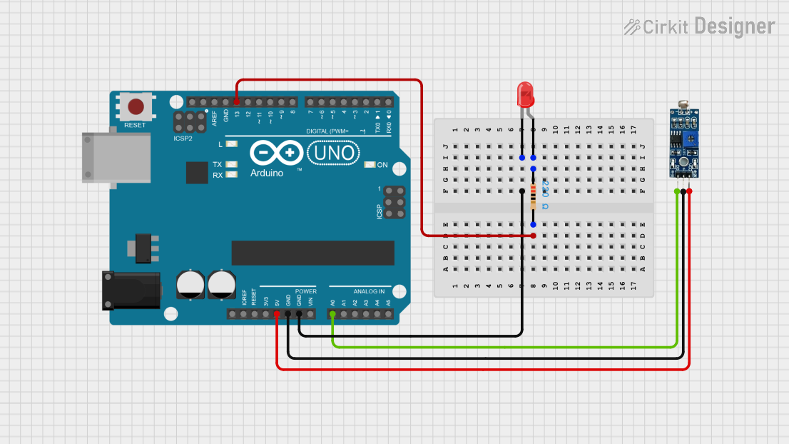
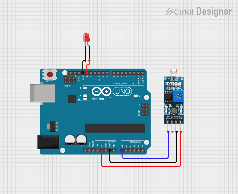
Example: Connecting to an Arduino UNO

Below is an example of how to use the photoresistor module with an Arduino UNO to read analog light intensity and control an LED based on a light threshold.

Circuit Connections

  • Connect the module's VCC to the Arduino's 5V pin.
  • Connect the module's GND to the Arduino's GND pin.
  • Connect the module's OUT pin to the Arduino's A0 pin (for analog input).
  • Connect an LED to pin D9 of the Arduino with a 220-ohm resistor in series.

Arduino Code

// Define pin connections
const int photoresistorPin = A0; // Analog pin connected to the module's OUT pin
const int ledPin = 9;           // Digital pin connected to the LED

void setup() {
  pinMode(ledPin, OUTPUT);      // Set LED pin as output
  Serial.begin(9600);           // Initialize serial communication for debugging
}

void loop() {
  int lightLevel = analogRead(photoresistorPin); // Read light intensity (0-1023)
  
  // Print the light level to the Serial Monitor
  Serial.print("Light Level: ");
  Serial.println(lightLevel);

  // Turn on the LED if light level is below a threshold (e.g., 500)
  if (lightLevel < 500) {
    digitalWrite(ledPin, HIGH); // Turn on LED
  } else {
    digitalWrite(ledPin, LOW);  // Turn off LED
  }

  delay(100); // Small delay for stability
}

Troubleshooting and FAQs

Common Issues and Solutions

  1. No Output Signal:

    • Cause: Incorrect wiring or insufficient power supply.
    • Solution: Double-check the connections and ensure the module is powered with 3.3V or 5V.
  2. Inconsistent Readings:

    • Cause: Electrical noise or unstable power supply.
    • Solution: Use decoupling capacitors near the module's power pins and ensure a stable power source.
  3. Digital Output Not Triggering:

    • Cause: Threshold not set correctly.
    • Solution: Adjust the potentiometer (if available) to set the desired light intensity threshold.
  4. Module Not Responding to Light Changes:

    • Cause: Photoresistor damaged or exposed to extreme conditions.
    • Solution: Replace the module and avoid exposing it to direct sunlight or high temperatures.

FAQs

Q: Can I use the photoresistor module with a 3.3V microcontroller like ESP32?
A: Yes, the module is compatible with 3.3V systems. Ensure the output voltage does not exceed the microcontroller's input voltage limits.

Q: How do I increase the sensitivity of the module?
A: If the module has a potentiometer, adjust it to increase sensitivity. Otherwise, consider using a more sensitive photoresistor.

Q: Can the module detect color or specific wavelengths of light?
A: No, the photoresistor module only detects the intensity of light and is not wavelength-specific. For color detection, use a color sensor module.

Q: Is the module suitable for outdoor use?
A: The module is not weatherproof. If used outdoors, enclose it in a protective, transparent casing to shield it from moisture and dust.