How to Use Color Sensor: Examples, Pinouts, and Specs
Introduction
The TCS3200 (or TCS3200-DB) is a programmable color light-to-frequency converter manufactured by ams OSRAM (formerly TAOS). This sensor is capable of detecting and measuring the color of an object or surface by converting light intensity into a frequency signal. It integrates an array of photodiodes with red, green, blue, and clear filters, along with a current-to-frequency converter, making it a versatile and compact solution for color detection.
Explore Projects Built with Color Sensor

Explore Projects Built with Color Sensor
Common Applications and Use Cases
- Robotics: Color-based navigation and object sorting.
- Industrial Automation: Quality control and color matching in manufacturing.
- Consumer Electronics: Color recognition in toys and gadgets.
- Medical Devices: Color analysis in diagnostic tools.
- DIY Projects: Arduino-based color detection systems.
Technical Specifications
Key Technical Details
- Supply Voltage: 2.7V to 5.5V
- Output: Square wave with frequency proportional to light intensity
- Current Consumption: 2mA (typical) at 5V
- Operating Temperature: -40°C to +85°C
- Photodiode Filters: Red, Green, Blue, and Clear
- Programmable Frequency Scaling: 100%, 20%, 2%, and Power Down
- Communication: Digital output (frequency signal)
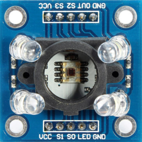
Pin Configuration and Descriptions
The TCS3200 sensor module typically has an 8-pin interface. Below is the pinout description:
| Pin | Name | Description |
|---|---|---|
| 1 | VCC | Power supply input (2.7V to 5.5V). |
| 2 | GND | Ground connection. |
| 3 | S0 | Frequency scaling input (see usage instructions for details). |
| 4 | S1 | Frequency scaling input (see usage instructions for details). |
| 5 | S2 | Photodiode filter selection input (see usage instructions for details). |
| 6 | S3 | Photodiode filter selection input (see usage instructions for details). |
| 7 | OUT | Output frequency signal proportional to the detected light intensity. |
| 8 | OE (EN) | Output enable (active low). Pull low to enable the output signal. |
Usage Instructions
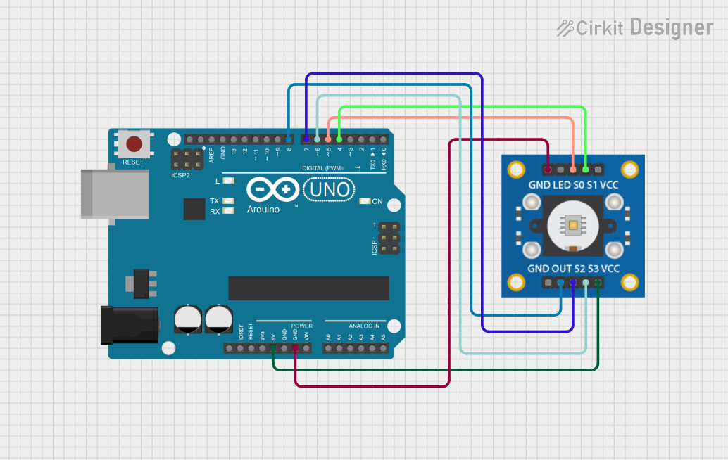
How to Use the TCS3200 in a Circuit
- Power the Sensor: Connect the VCC pin to a 5V power supply and GND to ground.
- Frequency Scaling: Use the S0 and S1 pins to set the output frequency scaling:
- S0 = LOW, S1 = LOW: Power down mode
- S0 = LOW, S1 = HIGH: 2% scaling
- S0 = HIGH, S1 = LOW: 20% scaling
- S0 = HIGH, S1 = HIGH: 100% scaling
- Filter Selection: Use the S2 and S3 pins to select the photodiode filter:
- S2 = LOW, S3 = LOW: Red filter
- S2 = LOW, S3 = HIGH: Blue filter
- S2 = HIGH, S3 = LOW: Clear (no filter)
- S2 = HIGH, S3 = HIGH: Green filter
- Output Signal: The OUT pin provides a square wave signal with a frequency proportional to the intensity of the selected color.
Important Considerations and Best Practices
- Ambient Light: Minimize ambient light interference by enclosing the sensor or using it in controlled lighting conditions.
- Output Enable: Ensure the OE pin is pulled low to enable the output signal.
- Frequency Scaling: Use lower scaling (e.g., 2%) for high-intensity light sources to avoid saturation.
- Calibration: Calibrate the sensor for your specific application to improve accuracy.
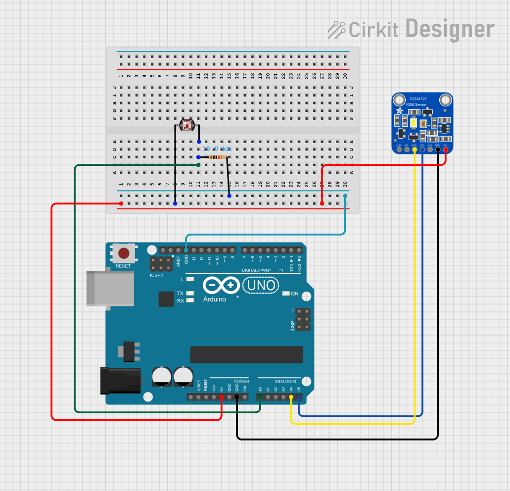
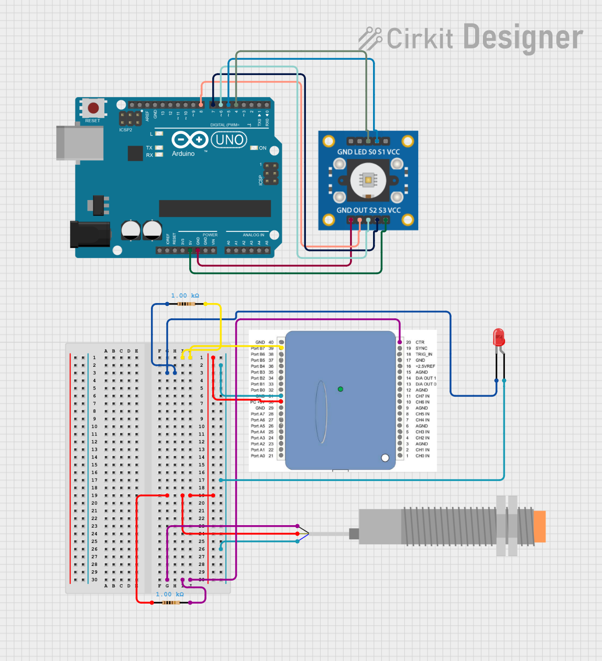
Example: Using TCS3200 with Arduino UNO
Below is an example Arduino sketch to read color data from the TCS3200 sensor:
// Pin definitions for TCS3200
#define S0 4  // Connect to S0 pin of TCS3200
#define S1 5  // Connect to S1 pin of TCS3200
#define S2 6  // Connect to S2 pin of TCS3200
#define S3 7  // Connect to S3 pin of TCS3200
#define OUT 8 // Connect to OUT pin of TCS3200

void setup() {
  // Set pin modes
  pinMode(S0, OUTPUT);
  pinMode(S1, OUTPUT);
  pinMode(S2, OUTPUT);
  pinMode(S3, OUTPUT);
  pinMode(OUT, INPUT);

  // Set frequency scaling to 20%
  digitalWrite(S0, HIGH);
  digitalWrite(S1, LOW);

  Serial.begin(9600); // Initialize serial communication
}

void loop() {
  // Read red color intensity
  digitalWrite(S2, LOW);
  digitalWrite(S3, LOW);
  int redFrequency = pulseIn(OUT, LOW);

  // Read green color intensity
  digitalWrite(S2, HIGH);
  digitalWrite(S3, HIGH);
  int greenFrequency = pulseIn(OUT, LOW);

  // Read blue color intensity
  digitalWrite(S2, LOW);
  digitalWrite(S3, HIGH);
  int blueFrequency = pulseIn(OUT, LOW);

  // Print the color frequencies
  Serial.print("Red: ");
  Serial.print(redFrequency);
  Serial.print(" Green: ");
  Serial.print(greenFrequency);
  Serial.print(" Blue: ");
  Serial.println(blueFrequency);

  delay(500); // Wait for 500ms before the next reading
}
Troubleshooting and FAQs
Common Issues and Solutions
No Output Signal:
- Ensure the OE pin is pulled low to enable the output.
- Verify the power supply voltage is within the specified range (2.7V to 5.5V).
Inaccurate Color Readings:
- Calibrate the sensor for your specific application.
- Reduce ambient light interference by shielding the sensor.
Output Frequency Too High or Low:
- Adjust the frequency scaling using the S0 and S1 pins.
- Use a lower scaling percentage for high-intensity light sources.
Sensor Not Responding:
- Check all connections and ensure the Arduino or microcontroller is properly powered.
- Verify that the correct pins are defined in the code.
FAQs
Q: Can the TCS3200 detect black or white?
A: Yes, the sensor can detect black (low frequency across all filters) and white (high frequency across all filters) based on the intensity of reflected light.
Q: How do I improve the accuracy of color detection?
A: Use proper calibration, minimize ambient light interference, and ensure consistent distance between the sensor and the object.
Q: Can I use the TCS3200 with a 3.3V microcontroller?
A: Yes, the TCS3200 operates within a supply voltage range of 2.7V to 5.5V, making it compatible with 3.3V systems.
This documentation provides a comprehensive guide to using the TCS3200 color sensor effectively in various applications.