How to Use TSR-3386UT Square Trimming Potentiometer: Examples, Pinouts, and Specs

Introduction
The TSR-3386UT Square Trimming Potentiometer is a compact and versatile variable resistor designed for fine-tuning and calibrating electrical circuits. It is commonly used in applications where precise voltage or current adjustments are necessary, such as in audio equipment, instrumentation, and hobby electronics projects. Its square form factor and three-terminal design make it suitable for printed circuit board (PCB) mounting and easy adjustment.
Explore Projects Built with TSR-3386UT Square Trimming Potentiometer
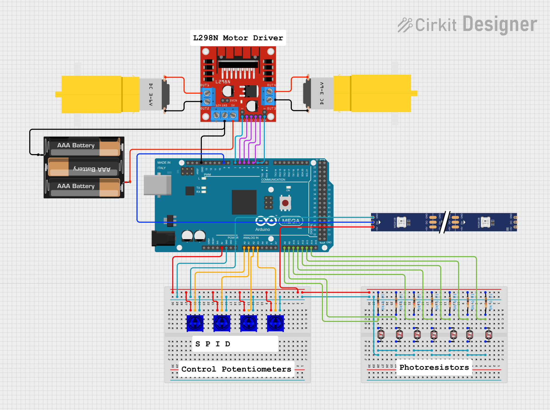


Explore Projects Built with TSR-3386UT Square Trimming Potentiometer
Technical Specifications
Key Technical Details
- Resistance Range: Typically available in various ranges (e.g., 1kΩ to 1MΩ)
- Tolerance: ±10% or better
- Power Rating: 0.5W (at 70°C)
- Voltage Rating: Maximum working voltage is linearly dependent on resistance (e.g., 300V for 1MΩ)
- Temperature Coefficient: Approximately ±100 ppm/°C
- Adjustment Type: Top adjustment using a flat-head screwdriver
- Mechanical Rotation: 270 degrees (nominal)
- Lifecycle: Up to 200 cycles
Pin Configuration and Descriptions
| Pin Number | Description |
|---|---|
| 1 | Counter-clockwise end (CCW) |
| 2 | Wiper (adjustable output) |
| 3 | Clockwise end (CW) |
Usage Instructions
Incorporating into a Circuit
To use the TSR-3386UT in a circuit, follow these steps:
- Identify the Resistance Range: Choose a potentiometer with a suitable resistance range for your application.
- Mounting: Securely mount the potentiometer onto the PCB, ensuring proper alignment of the pins.
- Wiring: Connect the pins to your circuit:
- Pin 1 to the lower voltage or ground (for voltage division).
- Pin 2 to the output where you need the variable voltage or signal.
- Pin 3 to the higher voltage (for voltage division).
- Adjustment: Use a flat-head screwdriver to adjust the wiper. Turn clockwise to increase and counter-clockwise to decrease the resistance.
Best Practices
- Avoid applying excessive force when adjusting the potentiometer to prevent damage.
- Do not exceed the power and voltage ratings to prevent overheating and potential failure.
- Use a stable and precise tool for adjustment to maintain the integrity of the potentiometer.
Troubleshooting and FAQs
Common Issues and Solutions
- Inconsistent Output: Ensure that the potentiometer is not damaged and that the wiper is making good contact.
- Noise in Signal: Check for loose connections and ensure that the potentiometer is free from dust and debris.
- Limited Adjustment Range: Verify that the potentiometer's resistance range is suitable for the application.
FAQs
Q: Can I use the TSR-3386UT for high-power applications? A: No, it is designed for low-power applications with a maximum power rating of 0.5W.
Q: How do I know if the potentiometer is at its maximum or minimum resistance? A: The resistance reaches its maximum when the wiper is turned fully clockwise and minimum when turned fully counter-clockwise.
Q: What tool should I use to adjust the TSR-3386UT? A: A small flat-head screwdriver is typically used for adjustment.
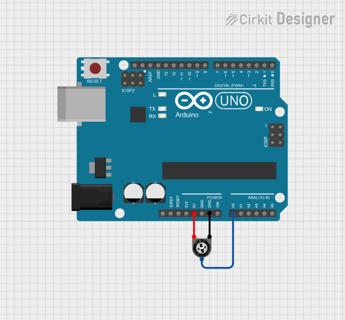
Example Code for Arduino UNO
// Connect the TSR-3386UT to an analog pin (e.g., A0) on the Arduino UNO.
// Pin 1 to GND, Pin 2 to A0, Pin 3 to 5V.

int potPin = A0; // Analog pin connected to the potentiometer wiper
int potValue = 0; // Variable to store the read value

void setup() {
  Serial.begin(9600); // Initialize serial communication at 9600 baud
}

void loop() {
  potValue = analogRead(potPin); // Read the potentiometer value
  Serial.println(potValue); // Print the value to the serial monitor
  delay(100); // Wait for 100 milliseconds before the next read
}
This example demonstrates how to read the value of the TSR-3386UT potentiometer using an Arduino UNO. The value read from the analog pin will vary as the potentiometer is adjusted, which can be observed on the serial monitor.