How to Use ATtiny85 20PU: Examples, Pinouts, and Specs
Introduction
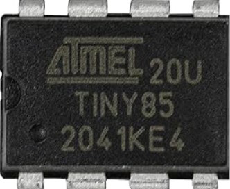
The ATtiny85 20PU is a small, low-power 8-bit microcontroller from the AVR family, designed for compact and efficient embedded systems. It features 8 KB of flash memory, 512 bytes of SRAM, and 6 general-purpose I/O pins. Its compact size, low power consumption, and ease of programming make it a popular choice for DIY electronics projects, wearable devices, and small-scale automation systems.
Explore Projects Built with ATtiny85 20PU


Explore Projects Built with ATtiny85 20PU
Common Applications
- DIY electronics projects
- Wearable devices
- IoT (Internet of Things) applications
- Small-scale robotics
- Sensor interfacing and data logging
- LED control and lighting systems
Technical Specifications
Key Technical Details
| Parameter | Value |
|---|---|
| Microcontroller Family | AVR |
| Flash Memory | 8 KB |
| SRAM | 512 bytes |
| EEPROM | 512 bytes |
| Operating Voltage | 2.7V - 5.5V |
| Maximum Clock Speed | 20 MHz |
| I/O Pins | 6 |
| ADC Channels | 4 (10-bit resolution) |
| PWM Channels | 2 |
| Package Type | PDIP-8 |
| Power Consumption | Low power (active and sleep modes) |
Pin Configuration and Descriptions
The ATtiny85 20PU comes in an 8-pin PDIP package. Below is the pinout and description:
| Pin Number | Pin Name | Description |
|---|---|---|
| 1 | PB5 (RESET) | Reset pin (active low) / GPIO |
| 2 | PB3 | GPIO / ADC3 / OC1B (PWM output) |
| 3 | PB4 | GPIO / ADC2 / OC1A (PWM output) |
| 4 | GND | Ground |
| 5 | PB0 | GPIO / ADC0 / MOSI (SPI) / SDA (I2C) |
| 6 | PB1 | GPIO / ADC1 / MISO (SPI) / SCL (I2C) |
| 7 | PB2 | GPIO / ADC1 / SCK (SPI) |
| 8 | VCC | Power supply (2.7V - 5.5V) |
Usage Instructions
How to Use the ATtiny85 20PU in a Circuit
- Power Supply: Connect the VCC pin to a 2.7V-5.5V power source and the GND pin to ground.
- Programming: Use an ISP (In-System Programmer) such as an Arduino UNO or a dedicated USB programmer to upload code to the ATtiny85.
- I/O Pins: Configure the GPIO pins (PB0-PB5) as input or output in your code. These pins can also be used for ADC, PWM, or communication protocols like SPI and I2C.
- Clock Source: The ATtiny85 can use its internal 8 MHz oscillator or an external clock source. Ensure the correct clock settings are configured in the fuse bits.
Important Considerations
- Pull-up Resistors: Enable internal pull-up resistors for input pins if needed.
- Power Consumption: Use sleep modes to reduce power consumption in battery-powered applications.
- Fuse Bits: Be cautious when setting fuse bits, as incorrect settings can disable programming or brick the microcontroller.
- Decoupling Capacitor: Place a 0.1 µF capacitor between VCC and GND to stabilize the power supply.
Example: Programming the ATtiny85 with Arduino UNO
The ATtiny85 can be programmed using the Arduino IDE and an Arduino UNO as an ISP. Below is an example of blinking an LED connected to PB0:
Circuit Setup
- Connect the ATtiny85 to the Arduino UNO as follows:
- ATtiny85 VCC to Arduino 5V
- ATtiny85 GND to Arduino GND
- ATtiny85 PB5 (RESET) to Arduino D10
- ATtiny85 PB0 to an LED (with a 220-ohm resistor in series)
- Install the ATtiny85 board package in the Arduino IDE.
Code Example
// Blink an LED on PB0 (Pin 5 on the ATtiny85)

void setup() {
  pinMode(0, OUTPUT); // Set PB0 as an output pin
}

void loop() {
  digitalWrite(0, HIGH); // Turn the LED on
  delay(1000);           // Wait for 1 second
  digitalWrite(0, LOW);  // Turn the LED off
  delay(1000);           // Wait for 1 second
}
Uploading the Code
- Select "ATtiny85" as the board in the Arduino IDE.
- Choose the appropriate clock speed (e.g., 8 MHz internal).
- Upload the code using the "Upload Using Programmer" option.
Troubleshooting and FAQs
Common Issues
The ATtiny85 is not responding to programming commands.
- Solution: Check the wiring between the programmer and the ATtiny85. Ensure the RESET pin is correctly connected.
- Tip: Verify that the correct board and clock settings are selected in the Arduino IDE.
The LED does not blink as expected.
- Solution: Double-check the pin number in the code and ensure the LED is connected to the correct pin.
- Tip: Use a multimeter to verify the voltage on the pin.
High power consumption in battery-powered applications.
- Solution: Use sleep modes in your code to reduce power consumption.
- Tip: Disable unused peripherals to save power.
Incorrect fuse bit settings.
- Solution: Use a high-voltage programmer to reset the fuse bits if the ATtiny85 becomes unresponsive.
- Tip: Double-check fuse bit configurations before programming.
FAQs
Can the ATtiny85 run at 20 MHz?
- Yes, but an external crystal oscillator is required for 20 MHz operation.
How do I use the ATtiny85 for I2C communication?
- Use the
Wirelibrary in the Arduino IDE. PB0 (SDA) and PB2 (SCL) are the I2C pins.
- Use the
Can I use the ATtiny85 without an external programmer?
- No, an external programmer or an Arduino UNO configured as an ISP is required to upload code.
What is the maximum current the I/O pins can source or sink?
- Each I/O pin can source or sink up to 40 mA, but it is recommended to stay below 20 mA for safe operation.
By following this documentation, you can effectively use the ATtiny85 20PU in your projects and troubleshoot common issues with ease.