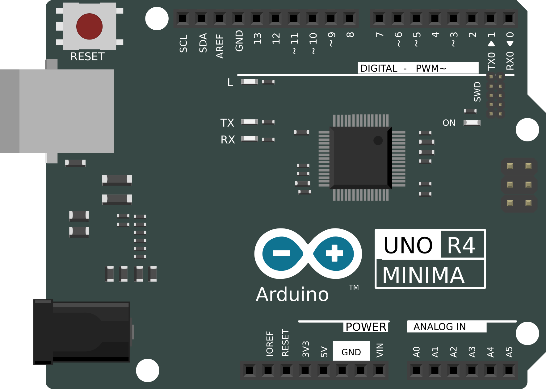
How to Use r4 minima: Examples, Pinouts, and Specs
Introduction
The R4 Minima is a specialized resistor designed for electronic circuits where low resistance and compact size are critical. Its minimal physical footprint makes it ideal for modern, space-constrained designs. Additionally, the R4 Minima offers precise current control, making it a reliable choice for applications requiring high accuracy and stability.
Explore Projects Built with r4 minima
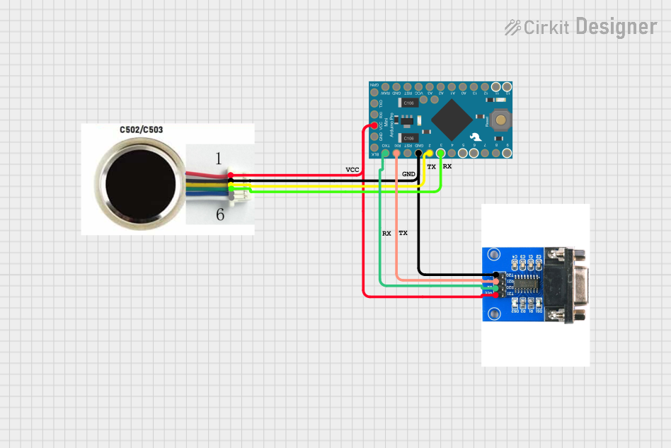
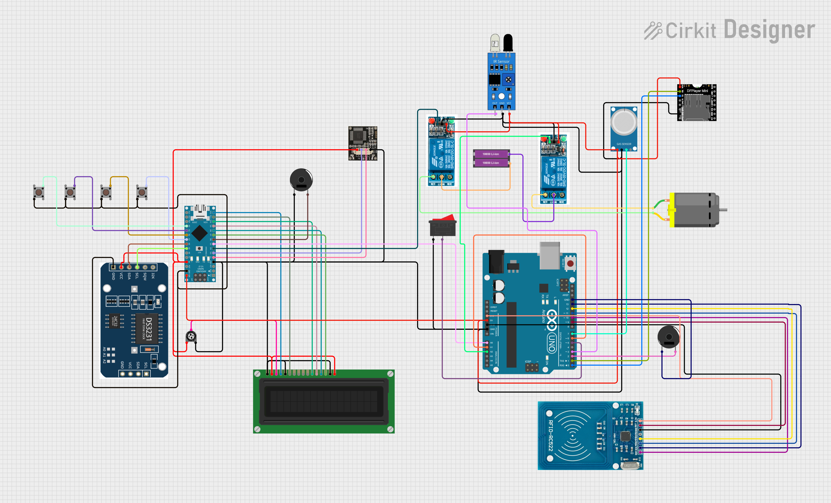
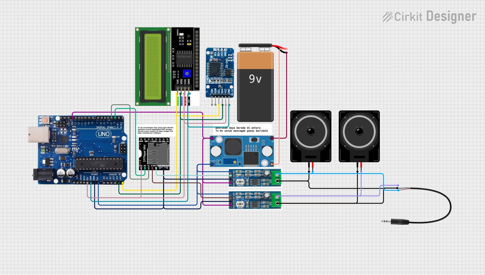

Explore Projects Built with r4 minima
Common Applications and Use Cases
- Compact electronic devices, such as smartphones and wearables
- Precision current sensing in power management circuits
- Voltage dividers in low-power applications
- Signal conditioning in analog circuits
- High-density printed circuit boards (PCBs)
Technical Specifications
The R4 Minima is available in various resistance values and power ratings to suit different applications. Below are the general technical specifications:
| Parameter | Value |
|---|---|
| Resistance Range | 0.1 Ω to 10 Ω |
| Tolerance | ±1%, ±5% |
| Power Rating | 0.125 W (1/8 W) to 0.25 W (1/4 W) |
| Temperature Coefficient | ±100 ppm/°C |
| Operating Temperature | -55°C to +125°C |
| Package Size | 0402, 0603, 0805 (SMD) |
Pin Configuration and Descriptions
The R4 Minima is a two-terminal passive component. Below is the pin configuration:
| Pin | Description |
|---|---|
| Pin 1 | Resistor terminal (connect to circuit) |
| Pin 2 | Resistor terminal (connect to circuit) |
Note: The R4 Minima is non-polarized, meaning there is no specific orientation required during installation.
Usage Instructions
How to Use the R4 Minima in a Circuit
- Determine the Required Resistance Value: Use Ohm's Law (V = IR) to calculate the resistance needed for your application.
- Select the Appropriate Power Rating: Ensure the resistor can handle the power dissipation in your circuit. Use the formula:
[ P = I^2 \times R ]
where (P) is power, (I) is current, and (R) is resistance. - Soldering the Resistor: Place the R4 Minima on the PCB pads and solder it carefully. Ensure proper alignment to avoid short circuits.
- Verify Connections: Use a multimeter to confirm the resistance value and check for proper connections.
Important Considerations and Best Practices
- Avoid Overheating: Excessive heat during soldering can damage the resistor or alter its resistance value.
- Power Dissipation: Ensure the resistor's power rating exceeds the expected power dissipation in the circuit.
- Parasitic Effects: In high-frequency circuits, the small size of the R4 Minima minimizes parasitic inductance and capacitance, but proper layout design is still essential.
- Storage: Store the resistors in a dry, anti-static environment to prevent damage.
Example: Using R4 Minima with an Arduino UNO
The R4 Minima can be used in current-sensing applications with an Arduino UNO. Below is an example of how to measure current using the R4 Minima as a shunt resistor:
// Example: Current measurement using R4 Minima and Arduino UNO
// Assumes a 0.1 Ω R4 Minima resistor is used as a shunt resistor

const int analogPin = A0; // Analog pin connected to the shunt resistor
const float shuntResistance = 0.1; // Resistance value in ohms

void setup() {
  Serial.begin(9600); // Initialize serial communication
}

void loop() {
  int sensorValue = analogRead(analogPin); // Read analog voltage
  float voltage = sensorValue * (5.0 / 1023.0); // Convert to voltage
  float current = voltage / shuntResistance; // Calculate current (I = V/R)

  // Print the current value to the Serial Monitor
  Serial.print("Current: ");
  Serial.print(current, 3); // Print current with 3 decimal places
  Serial.println(" A");

  delay(1000); // Wait 1 second before the next reading
}
Note: Ensure the voltage across the R4 Minima does not exceed the Arduino's analog input range (0-5V).
Troubleshooting and FAQs
Common Issues and Solutions
Incorrect Resistance Value Measured
- Cause: Poor soldering or damaged resistor.
- Solution: Re-solder the resistor or replace it with a new one.
Overheating of the Resistor
- Cause: Power dissipation exceeds the resistor's rating.
- Solution: Use a resistor with a higher power rating or reduce the current in the circuit.
Circuit Malfunction
- Cause: Incorrect resistor placement or value.
- Solution: Double-check the circuit design and verify the resistor's value with a multimeter.
FAQs
Q: Can the R4 Minima be used in high-frequency circuits?
A: Yes, its small size minimizes parasitic effects, making it suitable for high-frequency applications.Q: How do I choose the correct tolerance for my application?
A: For precision applications, use resistors with a ±1% tolerance. For general use, ±5% is sufficient.Q: Is the R4 Minima available in through-hole packages?
A: No, the R4 Minima is designed as a surface-mount device (SMD) for compact designs.
By following this documentation, you can effectively integrate the R4 Minima into your electronic projects.