How to Use NOT GATE: Examples, Pinouts, and Specs
Introduction
The SN7404N is a NOT gate, also known as an inverter, manufactured by TTL. A NOT gate is a fundamental digital logic gate that outputs the opposite value of its input. If the input is 1 (high), the output is 0 (low), and vice versa. This component is widely used in digital circuits for signal inversion, logic operations, and various other applications.
Explore Projects Built with NOT GATE
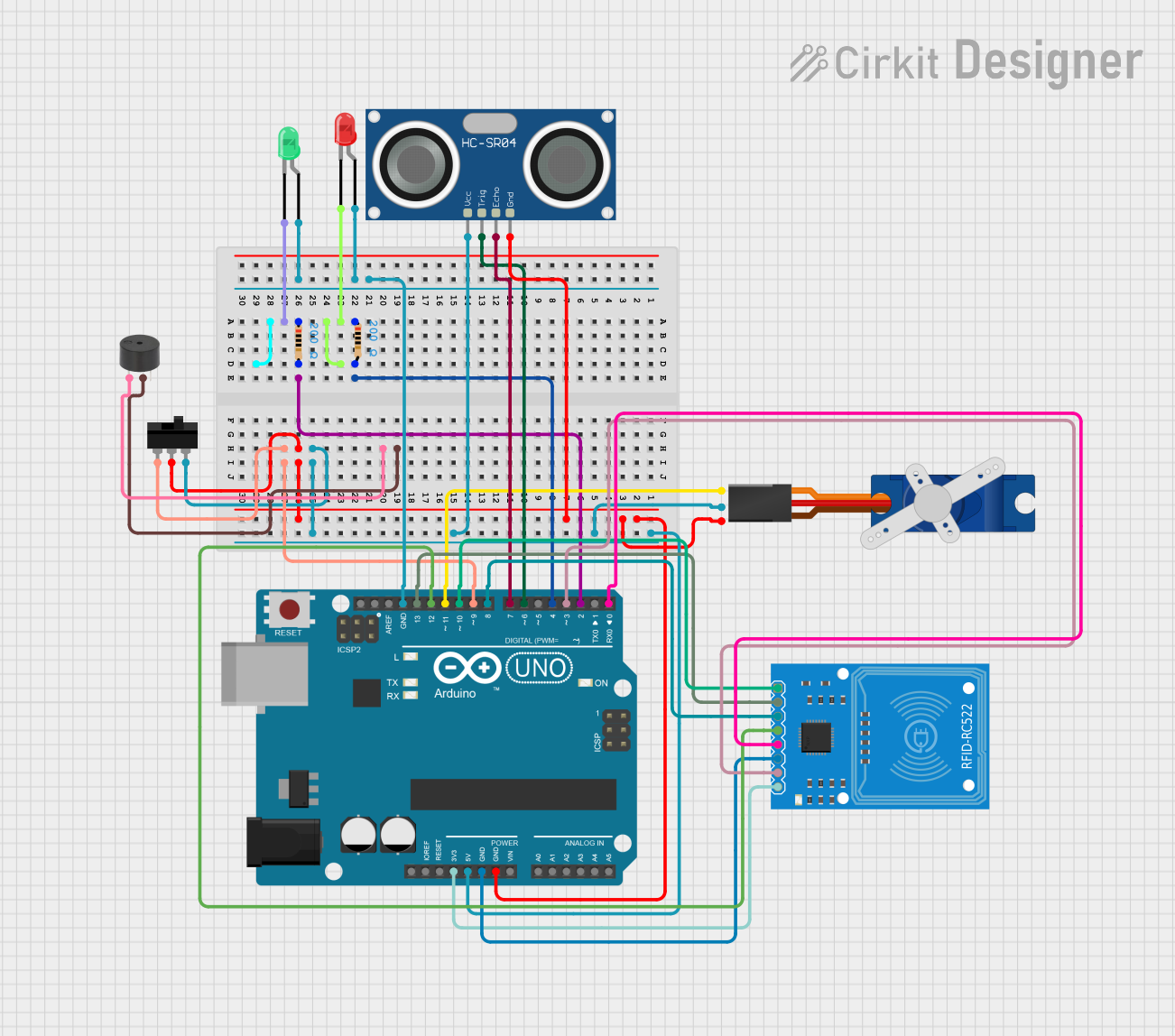

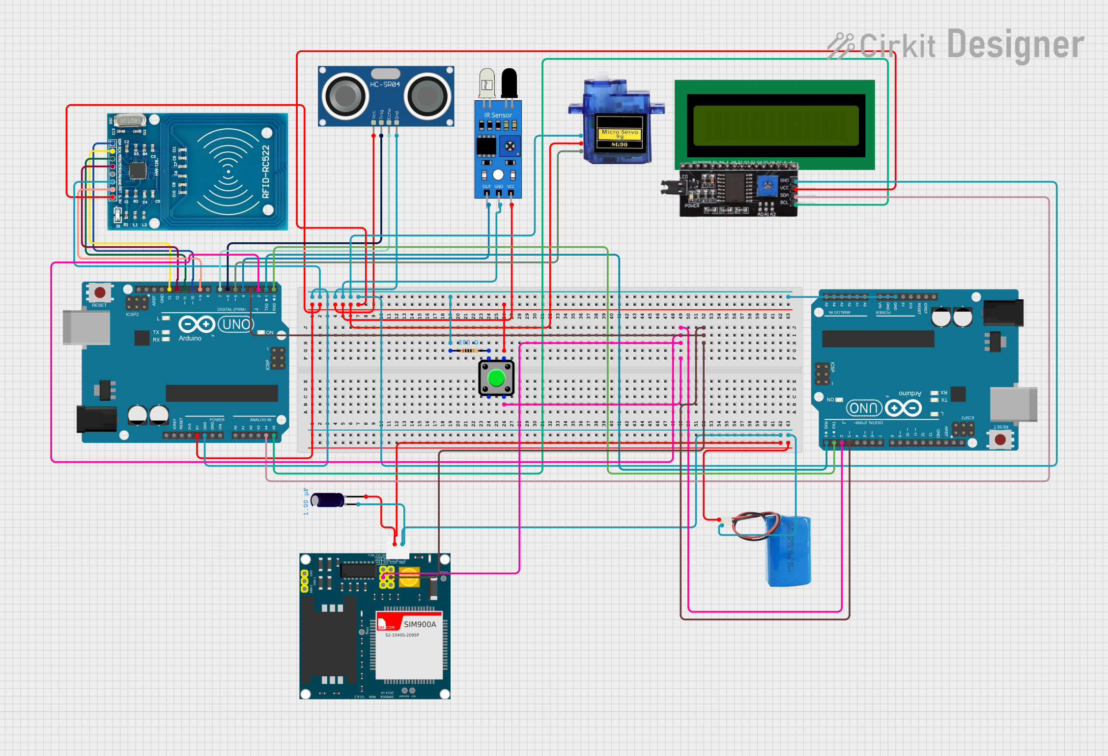
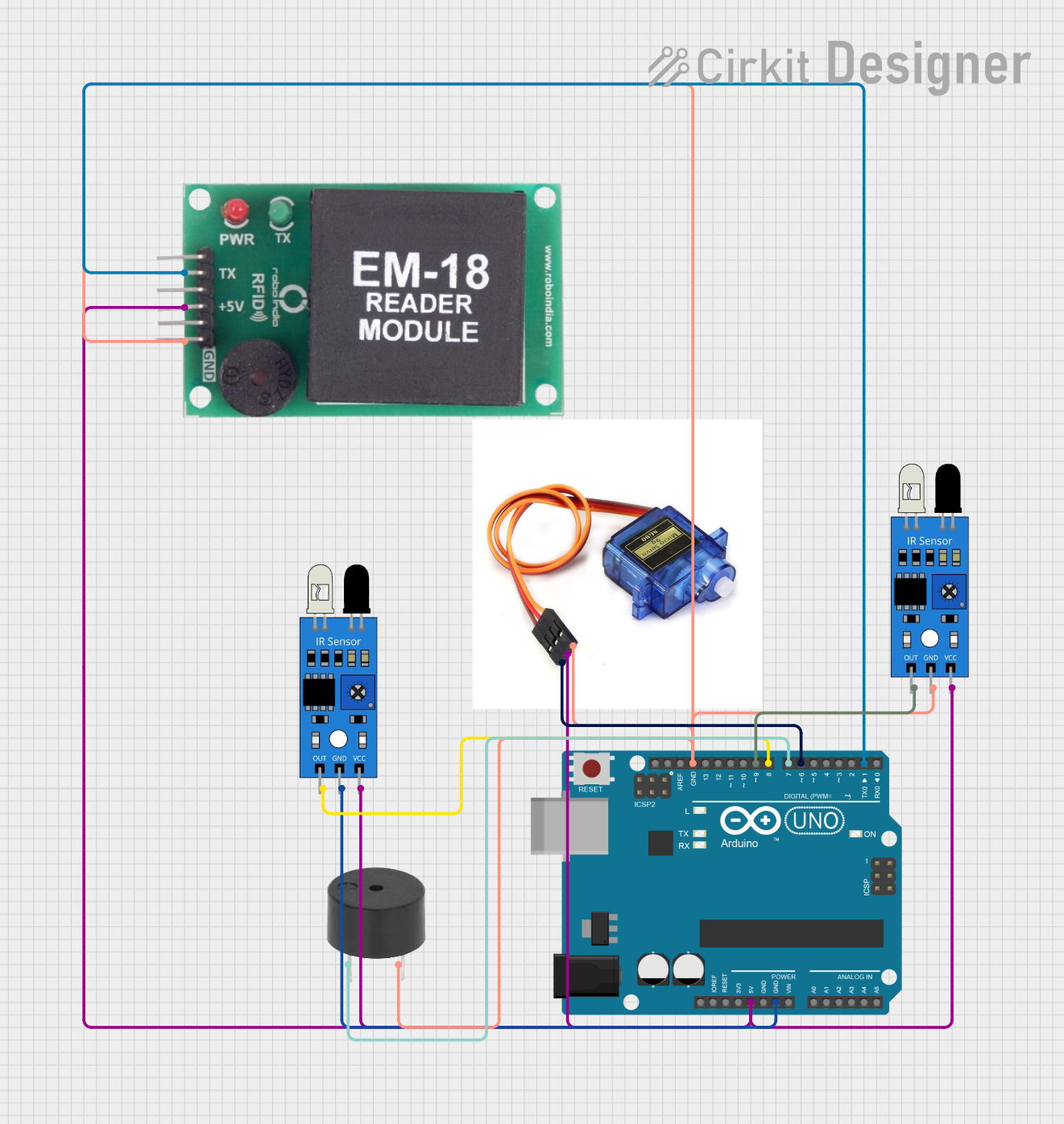
Explore Projects Built with NOT GATE
Common Applications and Use Cases
- Signal Inversion: Inverting the logic level of a signal.
- Logic Operations: Used in combination with other logic gates to perform complex logic functions.
- Oscillators: Used in oscillator circuits to generate clock signals.
- Microcontroller Interfacing: Commonly used with microcontrollers like Arduino for various digital logic applications.
Technical Specifications
Key Technical Details
| Parameter | Value |
|---|---|
| Supply Voltage (Vcc) | 4.75V to 5.25V |
| Input Voltage (VI) | 0V to 5V |
| Output Voltage (VO) | 0V to 5V |
| High-Level Input Voltage (VIH) | 2V (min) |
| Low-Level Input Voltage (VIL) | 0.8V (max) |
| High-Level Output Voltage (VOH) | 2.4V (min) |
| Low-Level Output Voltage (VOL) | 0.4V (max) |
| High-Level Output Current (IOH) | -0.4mA |
| Low-Level Output Current (IOL) | 16mA |
| Power Dissipation | 500mW |
| Operating Temperature Range | 0°C to 70°C |
Pin Configuration and Descriptions
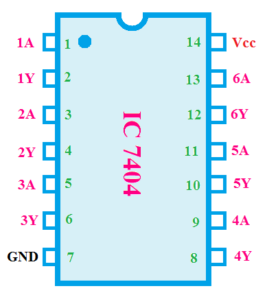
The SN7404N NOT gate comes in a 14-pin Dual In-line Package (DIP). The pin configuration is as follows:
| Pin Number | Pin Name | Description |
|---|---|---|
| 1 | 1A | Input for Gate 1 |
| 2 | 1Y | Output for Gate 1 |
| 3 | 2A | Input for Gate 2 |
| 4 | 2Y | Output for Gate 2 |
| 5 | 3A | Input for Gate 3 |
| 6 | 3Y | Output for Gate 3 |
| 7 | GND | Ground |
| 8 | 4Y | Output for Gate 4 |
| 9 | 4A | Input for Gate 4 |
| 10 | 5Y | Output for Gate 5 |
| 11 | 5A | Input for Gate 5 |
| 12 | 6Y | Output for Gate 6 |
| 13 | 6A | Input for Gate 6 |
| 14 | Vcc | Supply Voltage |
Usage Instructions
How to Use the Component in a Circuit
- Power Supply: Connect pin 14 (Vcc) to a 5V power supply and pin 7 (GND) to ground.
- Input Connection: Connect the input signal to one of the input pins (1A, 2A, 3A, 4A, 5A, or 6A).
- Output Connection: The inverted output will be available at the corresponding output pin (1Y, 2Y, 3Y, 4Y, 5Y, or 6Y).
Important Considerations and Best Practices
- Decoupling Capacitor: Place a 0.1µF decoupling capacitor between Vcc and GND to filter out noise.
- Unused Inputs: Connect any unused inputs to GND to prevent floating inputs, which can cause erratic behavior.
- Current Limiting: Ensure that the output current does not exceed the specified limits to avoid damaging the component.
Example Circuit with Arduino UNO
Here is an example of how to use the SN7404N with an Arduino UNO to invert a digital signal:
// Define the input and output pins
const int inputPin = 2;  // Input signal from Arduino
const int outputPin = 3; // Inverted output signal

void setup() {
  pinMode(inputPin, OUTPUT); // Set inputPin as output
  pinMode(outputPin, INPUT); // Set outputPin as input
}

void loop() {
  digitalWrite(inputPin, HIGH); // Set inputPin to HIGH
  delay(1000);                  // Wait for 1 second
  digitalWrite(inputPin, LOW);  // Set inputPin to LOW
  delay(1000);                  // Wait for 1 second
}
Troubleshooting and FAQs
Common Issues Users Might Face
No Output Signal:
- Solution: Check the power supply connections (Vcc and GND). Ensure the input signal is within the specified voltage range.
Erratic Behavior:
- Solution: Ensure all unused inputs are connected to GND. Add a decoupling capacitor between Vcc and GND.
Overheating:
- Solution: Check the output current to ensure it does not exceed the specified limits. Reduce the load if necessary.
Solutions and Tips for Troubleshooting
- Verify Connections: Double-check all connections, especially power supply and ground.
- Use a Multimeter: Measure the input and output voltages to ensure they are within the specified ranges.
- Check for Shorts: Inspect the circuit for any short circuits or solder bridges.
By following this documentation, users can effectively utilize the SN7404N NOT gate in their digital circuits, ensuring reliable and efficient performance.