
How to Use W5500 w/ Level Shift: Examples, Pinouts, and Specs
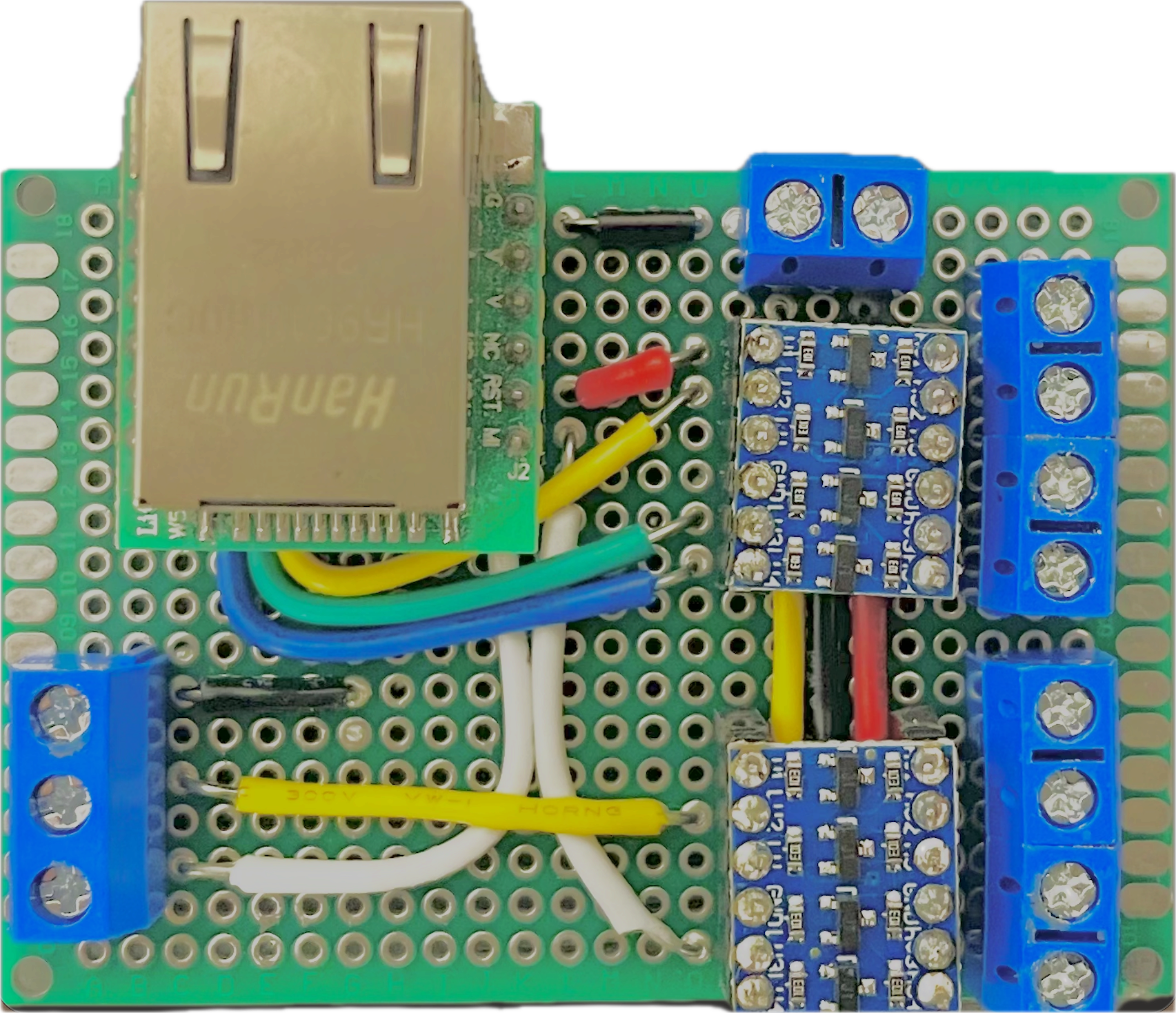
 Design with W5500 w/ Level Shift in Cirkit Designer
Introduction
The W5500 is a hardwired TCP/IP embedded Ethernet controller designed to simplify the process of connecting microcontrollers to the internet. It integrates a full TCP/IP stack, Ethernet MAC, and PHY, providing a reliable and efficient solution for network communication. The inclusion of level shift circuitry ensures compatibility between devices operating at different voltage levels, making it suitable for a wide range of microcontroller platforms.
Explore Projects Built with W5500 w/ Level Shift
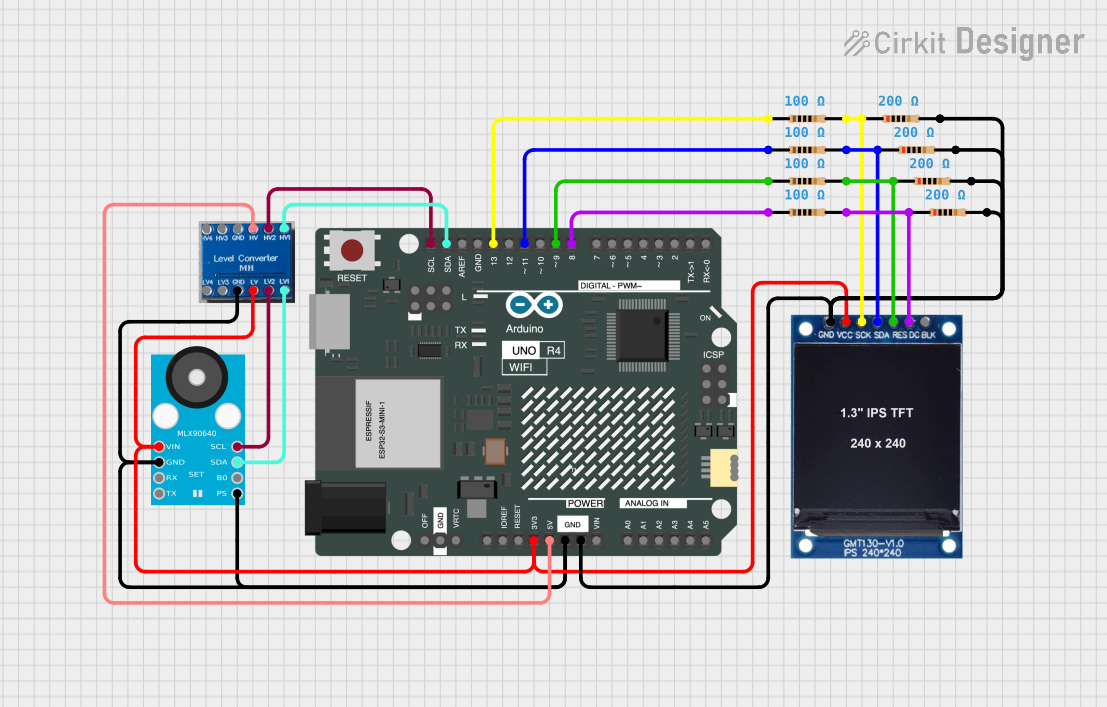 Open Project in Cirkit Designer
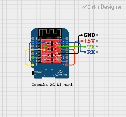 Open Project in Cirkit Designer
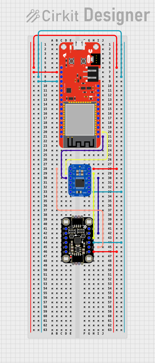 Open Project in Cirkit Designer
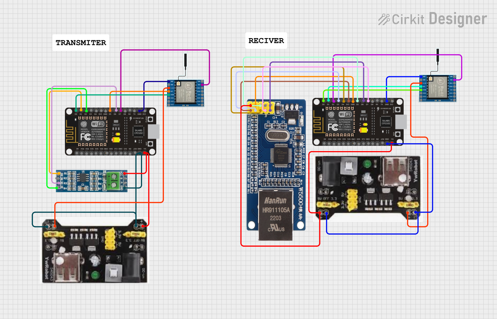 Open Project in Cirkit Designer
Explore Projects Built with W5500 w/ Level Shift
Open Project in Cirkit DesignerOpen Project in Cirkit DesignerOpen Project in Cirkit DesignerOpen Project in Cirkit DesignerCommon Applications and Use Cases
- IoT (Internet of Things) devices
- Home automation systems
- Industrial control and monitoring
- Network-enabled embedded systems
- Data logging and remote monitoring
Technical Specifications
Key Technical Details
- Operating Voltage: 3.3V (logic level shifting supports 5V systems)
- Current Consumption: 132 mA (typical)
- Network Protocols Supported: TCP, UDP, ICMP, IPv4, ARP, IGMP, PPPoE
- Ethernet Speed: 10/100 Mbps
- SPI Interface: Up to 80 MHz
- Integrated Memory: 32 KB for TX/RX buffers
- Operating Temperature: -40°C to +85°C
- Package: LQFP-48
Pin Configuration and Descriptions
The W5500 module typically includes the following pins:
| Pin Name | Type | Description |
|---|---|---|
| VCC | Power | Power supply input (3.3V). |
| GND | Ground | Ground connection. |
| SCS | Digital Input | SPI chip select (active low). |
| SCLK | Digital Input | SPI clock input. |
| MOSI | Digital Input | SPI master-out, slave-in data line. |
| MISO | Digital Output | SPI master-in, slave-out data line. |
| INT | Digital Output | Interrupt output (active low). |
| RST | Digital Input | Reset input (active low). |
| LINK_LED | Digital Output | Indicates Ethernet link status. |
| ACT_LED | Digital Output | Indicates Ethernet activity. |
Usage Instructions
How to Use the W5500 in a Circuit
- Power Supply: Connect the VCC pin to a 3.3V power source and GND to ground. If using a 5V microcontroller, ensure the level shift circuitry is properly configured.
- SPI Interface: Connect the SPI pins (SCS, SCLK, MOSI, MISO) to the corresponding SPI pins on your microcontroller.
- Reset and Interrupt: Connect the RST pin to a GPIO pin on your microcontroller for manual resets. The INT pin can be used to detect events such as received packets.
- Ethernet Connection: Attach an Ethernet cable to the RJ45 connector on the module.
- Pull-Up Resistors: Ensure pull-up resistors are used on the SPI lines if required by your microcontroller.
Important Considerations and Best Practices
- Use decoupling capacitors (e.g., 0.1 µF) near the VCC pin to stabilize the power supply.
- Ensure the SPI clock frequency does not exceed 80 MHz.
- Use proper grounding techniques to minimize noise and interference.
- If using a 5V microcontroller, verify that the level shift circuitry is functioning correctly to avoid damaging the W5500.
Example Code for Arduino UNO
Below is an example of how to use the W5500 with an Arduino UNO to establish a basic Ethernet connection:
#include <SPI.h>
#include <Ethernet.h>

// MAC address for the Ethernet shield
byte mac[] = { 0xDE, 0xAD, 0xBE, 0xEF, 0xFE, 0xED };

// IP address for the device
IPAddress ip(192, 168, 1, 177);

// Initialize the Ethernet server on port 80
EthernetServer server(80);

void setup() {
  // Start the serial communication for debugging
  Serial.begin(9600);

  // Initialize the Ethernet connection
  if (Ethernet.begin(mac) == 0) {
    Serial.println("Failed to configure Ethernet using DHCP");
    // Manually configure the IP address if DHCP fails
    Ethernet.begin(mac, ip);
  }

  // Start the server
  server.begin();
  Serial.print("Server is at ");
  Serial.println(Ethernet.localIP());
}

void loop() {
  // Listen for incoming clients
  EthernetClient client = server.available();
  if (client) {
    Serial.println("New client connected");
    // Wait until the client sends data
    while (client.connected()) {
      if (client.available()) {
        char c = client.read();
        Serial.write(c); // Echo the received data to the serial monitor

        // Respond to the client
        server.write("HTTP/1.1 200 OK\r\n");
        server.write("Content-Type: text/html\r\n\r\n");
        server.write("<h1>Hello from W5500!</h1>");
        break;
      }
    }
    // Close the connection
    client.stop();
    Serial.println("Client disconnected");
  }
}
Notes:
- Replace the
macandipvalues with those appropriate for your network. - Ensure the Ethernet library is installed in your Arduino IDE.
Troubleshooting and FAQs
Common Issues and Solutions
No Ethernet Connection:
- Verify that the Ethernet cable is securely connected.
- Check the LINK_LED and ACT_LED for activity.
- Ensure the MAC and IP addresses are correctly configured.
SPI Communication Fails:
- Confirm that the SPI pins are correctly connected.
- Check the SPI clock frequency and ensure it does not exceed 80 MHz.
- Verify that the SCS pin is properly toggled during communication.
Module Not Responding:
- Ensure the RST pin is not held low.
- Check the power supply voltage and ensure it is stable at 3.3V.
- Inspect the level shift circuitry for proper operation.
Slow Network Performance:
- Use shorter Ethernet cables to reduce signal degradation.
- Check for excessive traffic on the network.
FAQs
Q: Can the W5500 work with 5V microcontrollers?
A: Yes, the level shift circuitry allows the W5500 to interface with 5V microcontrollers safely.
Q: What is the maximum Ethernet speed supported?
A: The W5500 supports 10/100 Mbps Ethernet speeds.
Q: Do I need external memory for the W5500?
A: No, the W5500 has an integrated 32 KB memory for TX/RX buffers.
Q: Can I use the W5500 with platforms other than Arduino?
A: Yes, the W5500 can be used with any platform that supports SPI communication, such as Raspberry Pi, STM32, and ESP32.