How to Use BoSL board 0.5: Examples, Pinouts, and Specs
Introduction
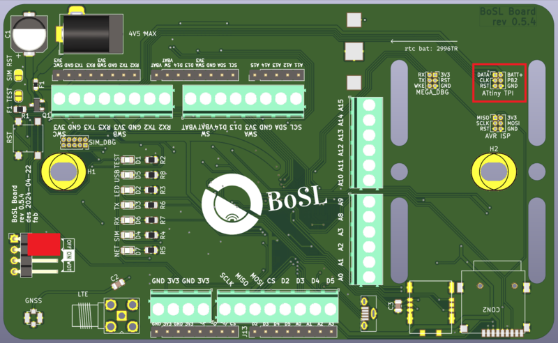
The BoSL Board 0.5, manufactured by BoSL, is a compact and versatile prototyping board designed for building and testing digital logic circuits. It features a grid of holes that allow for easy placement of components and connections, making it an ideal tool for engineers, students, and hobbyists working on digital logic projects. The board is designed to simplify the prototyping process, enabling quick assembly and testing of circuits without the need for soldering.
Explore Projects Built with BoSL board 0.5
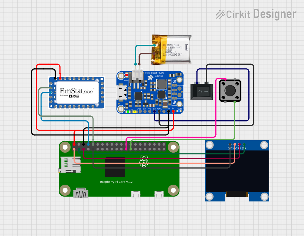

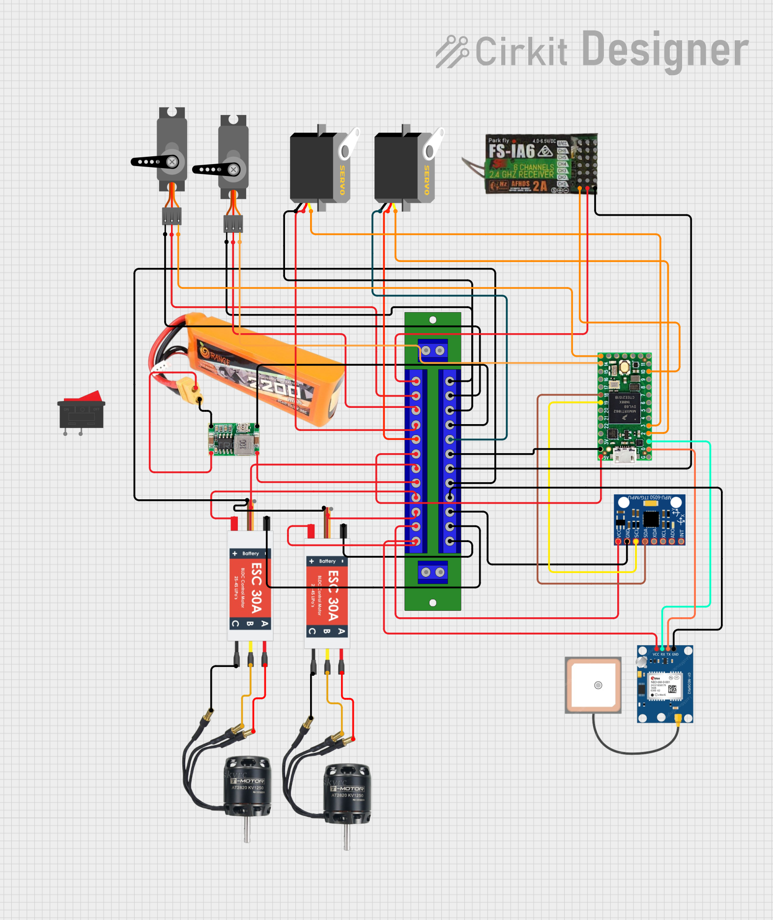

Explore Projects Built with BoSL board 0.5
Common Applications and Use Cases
- Prototyping digital logic circuits for educational or professional purposes.
- Testing and debugging small-scale digital systems.
- Building combinational and sequential logic circuits.
- Creating temporary setups for experimentation with logic gates, flip-flops, and other digital components.
Technical Specifications
The BoSL Board 0.5 is designed with the following technical specifications:
| Specification | Details |
|---|---|
| Manufacturer | BoSL |
| Part ID | 0.5 |
| Board Dimensions | 50mm x 50mm |
| Hole Grid Size | 0.1-inch (2.54mm) pitch |
| Material | FR4 (Flame Retardant 4) |
| Hole Plating | Non-plated |
| Maximum Voltage | 50V |
| Maximum Current | 1A |
| Compatibility | Compatible with standard through-hole components and jumper wires |
Pin Configuration and Descriptions
The BoSL Board 0.5 does not have predefined pins, as it is a prototyping board. Instead, it features a grid of holes with the following characteristics:
| Feature | Description |
|---|---|
| Hole Grid | 0.1-inch (2.54mm) spacing, compatible with standard DIP components |
| Power Rails | Two rows of holes along the edges for power and ground connections |
| Component Placement Area | Central grid for placing and connecting components |
Usage Instructions
How to Use the BoSL Board 0.5 in a Circuit
- Plan Your Circuit: Sketch the circuit diagram on paper or using software before assembling it on the board.
- Place Components: Insert through-hole components (e.g., resistors, capacitors, ICs) into the grid holes.
- Connect Components: Use jumper wires or solderless connectors to establish connections between components.
- Power the Circuit: Connect the power supply to the designated power rails on the board.
- Test the Circuit: Use a multimeter or logic analyzer to verify the functionality of your circuit.
Important Considerations and Best Practices
- Avoid Overloading: Ensure that the voltage and current do not exceed the board's maximum ratings (50V and 1A).
- Use Proper Tools: Use a breadboard-friendly jumper wire kit for clean and reliable connections.
- Organize Connections: Keep wires short and organized to minimize noise and interference.
- Label Components: Use labels or a reference diagram to keep track of component placements.
- Static Precautions: Handle sensitive components with care to avoid damage from electrostatic discharge (ESD).
Example: Connecting a Logic Gate to an Arduino UNO
The BoSL Board 0.5 can be used to prototype circuits that interface with an Arduino UNO. Below is an example of connecting a 74HC00 NAND gate to an Arduino UNO:
Circuit Setup
- Place the 74HC00 IC on the BoSL Board 0.5.
- Connect the VCC and GND pins of the IC to the power rails.
- Use jumper wires to connect the input pins of the NAND gate to Arduino digital pins.
- Connect the output pin of the NAND gate to an LED with a current-limiting resistor.
Arduino Code
// Example code to control a NAND gate using Arduino UNO
// This code toggles the inputs of a NAND gate and reads the output.

const int inputPin1 = 2; // Connect to NAND gate input A
const int inputPin2 = 3; // Connect to NAND gate input B
const int outputPin = 4; // Connect to NAND gate output

void setup() {
  pinMode(inputPin1, OUTPUT); // Set input A as output
  pinMode(inputPin2, OUTPUT); // Set input B as output
  pinMode(outputPin, INPUT);  // Set output pin as input
  Serial.begin(9600);         // Initialize serial communication
}

void loop() {
  digitalWrite(inputPin1, HIGH); // Set input A to HIGH
  digitalWrite(inputPin2, LOW);  // Set input B to LOW
  delay(1000);                   // Wait for 1 second

  int outputState = digitalRead(outputPin); // Read NAND gate output
  Serial.print("NAND Output: ");
  Serial.println(outputState); // Print output state to Serial Monitor

  digitalWrite(inputPin1, LOW); // Set input A to LOW
  digitalWrite(inputPin2, HIGH); // Set input B to HIGH
  delay(1000);                   // Wait for 1 second
}
Troubleshooting and FAQs
Common Issues Users Might Face
Loose Connections: Components or wires may not be securely connected to the board.
- Solution: Double-check all connections and ensure components are firmly seated in the holes.
Short Circuits: Adjacent wires or components may accidentally touch, causing a short circuit.
- Solution: Inspect the board for any unintended connections and separate them.
Component Damage: Overvoltage or incorrect connections can damage components.
- Solution: Verify the circuit design and ensure components are used within their rated specifications.
Intermittent Connections: Poor-quality jumper wires may cause intermittent issues.
- Solution: Use high-quality jumper wires and test connections with a multimeter.
FAQs
Q: Can I solder components to the BoSL Board 0.5?
A: No, the BoSL Board 0.5 is designed for solderless prototyping. Use a solderable prototyping board if permanent connections are required.
Q: Is the board compatible with surface-mount devices (SMD)?
A: The BoSL Board 0.5 is designed for through-hole components. SMD components require an adapter or a different board.
Q: Can I use the board for analog circuits?
A: While the board is optimized for digital logic circuits, it can also be used for simple analog circuits within the voltage and current limits.
Q: How do I clean the board after use?
A: Use a soft brush or compressed air to remove dust and debris. Avoid using liquids that may damage the board.