Cirkit Designer Logo
Cirkit Designer
Your all-in-one circuit design IDE
Home / 
Component Documentation

How to Use regulator: Examples, Pinouts, and Specs

Image of regulator
Cirkit Designer LogoDesign with regulator in Cirkit Designer

Introduction

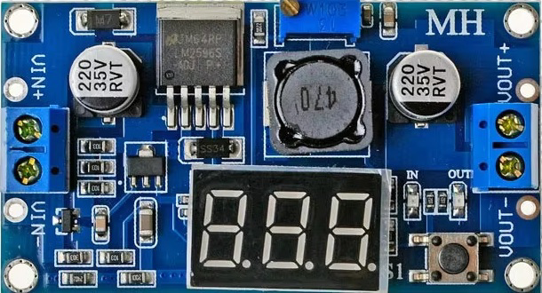
A regulator is an electronic component designed to maintain a constant output voltage or current, regardless of fluctuations in input voltage or load conditions. This ensures stable and reliable operation of electronic circuits, protecting sensitive components from damage caused by voltage variations. Regulators are widely used in power supply systems, embedded systems, and various electronic devices to provide a steady voltage source.

Explore Projects Built with regulator

Use Cirkit Designer to design, explore, and prototype these projects online. Some projects support real-time simulation. Click "Open Project" to start designing instantly!
Solar-Powered Battery Charging System with XL6009 Voltage Regulator
Image of SISTEMA DE ALIMENTACION Y CARGA SENSORES DS18B20 Y SENSOR DE TURBIDEZ: A project utilizing regulator in a practical application
This circuit features a solar panel ('Do solara') connected to a voltage regulator ('XL6009 Voltage Regulator') to stabilize the output voltage. The regulated voltage is available at a terminal block ('Terminal PCB 2 Pin') for further use. Additionally, a Li-ion battery ('18650 Li-ion Battery') is connected to the solar panel for charging, with the solar panel's output also routed through the voltage regulator.
Cirkit Designer LogoOpen Project in Cirkit Designer
LM317 Voltage Regulator Circuit for Adjustable Power Supply with Transformer and Diodes
Image of 12V BULB LIGHT DIMMER CIRCUIT: A project utilizing regulator in a practical application
This circuit is a regulated power supply that converts AC voltage to a stable DC voltage. It uses a transformer to step down the AC voltage, diodes for rectification, an electrolytic capacitor for smoothing, and an LM317 voltage regulator to provide a stable output voltage, which is adjustable via a potentiometer. The output powers a bulb.
Cirkit Designer LogoOpen Project in Cirkit Designer
Battery-Powered LED Control Circuit with Potentiometer and Transistors
Image of STROBE LIGHTS: A project utilizing regulator in a practical application
This circuit is a regulated power supply with a 12V battery input, a 7805 voltage regulator providing a 5V output, and a potentiometer for adjustable voltage control. It includes transistors and resistors for current regulation and an LED indicator to show the operational status.
Cirkit Designer LogoOpen Project in Cirkit Designer
AC to DC Power Supply with Voltage Regulation and Multimeter Monitoring
Image of Copy of 8 volt AC to DC convertor (1): A project utilizing regulator in a practical application
This circuit is a power supply that converts AC voltage to a regulated DC output. An AC supply is connected to a transformer, which steps down the voltage to a lower AC voltage. This lower AC voltage is then rectified by a bridge rectifier into pulsating DC, filtered by an electrolytic capacitor to reduce ripple, and finally regulated by a 7808 voltage regulator to provide a stable 8V DC output. A multimeter is connected to measure the output voltage of the regulator.
Cirkit Designer LogoOpen Project in Cirkit Designer

Explore Projects Built with regulator

Use Cirkit Designer to design, explore, and prototype these projects online. Some projects support real-time simulation. Click "Open Project" to start designing instantly!
Image of SISTEMA DE ALIMENTACION Y CARGA SENSORES DS18B20 Y SENSOR DE TURBIDEZ: A project utilizing regulator in a practical application
Solar-Powered Battery Charging System with XL6009 Voltage Regulator
This circuit features a solar panel ('Do solara') connected to a voltage regulator ('XL6009 Voltage Regulator') to stabilize the output voltage. The regulated voltage is available at a terminal block ('Terminal PCB 2 Pin') for further use. Additionally, a Li-ion battery ('18650 Li-ion Battery') is connected to the solar panel for charging, with the solar panel's output also routed through the voltage regulator.
Cirkit Designer LogoOpen Project in Cirkit Designer
Image of 12V BULB LIGHT DIMMER CIRCUIT: A project utilizing regulator in a practical application
LM317 Voltage Regulator Circuit for Adjustable Power Supply with Transformer and Diodes
This circuit is a regulated power supply that converts AC voltage to a stable DC voltage. It uses a transformer to step down the AC voltage, diodes for rectification, an electrolytic capacitor for smoothing, and an LM317 voltage regulator to provide a stable output voltage, which is adjustable via a potentiometer. The output powers a bulb.
Cirkit Designer LogoOpen Project in Cirkit Designer
Image of STROBE LIGHTS: A project utilizing regulator in a practical application
Battery-Powered LED Control Circuit with Potentiometer and Transistors
This circuit is a regulated power supply with a 12V battery input, a 7805 voltage regulator providing a 5V output, and a potentiometer for adjustable voltage control. It includes transistors and resistors for current regulation and an LED indicator to show the operational status.
Cirkit Designer LogoOpen Project in Cirkit Designer
Image of Copy of 8 volt AC to DC convertor (1): A project utilizing regulator in a practical application
AC to DC Power Supply with Voltage Regulation and Multimeter Monitoring
This circuit is a power supply that converts AC voltage to a regulated DC output. An AC supply is connected to a transformer, which steps down the voltage to a lower AC voltage. This lower AC voltage is then rectified by a bridge rectifier into pulsating DC, filtered by an electrolytic capacitor to reduce ripple, and finally regulated by a 7808 voltage regulator to provide a stable 8V DC output. A multimeter is connected to measure the output voltage of the regulator.
Cirkit Designer LogoOpen Project in Cirkit Designer

Common Applications and Use Cases

  • Power supply circuits for microcontrollers and sensors
  • Voltage stabilization in battery-powered devices
  • Protection of sensitive electronic components
  • DC-DC or AC-DC conversion systems
  • Industrial and automotive electronics

Technical Specifications

The technical specifications of a regulator can vary depending on its type (e.g., linear or switching regulator). Below is an example of a typical linear voltage regulator (e.g., 7805):

Key Technical Details

  • Input Voltage Range: 7V to 35V
  • Output Voltage: 5V (fixed)
  • Output Current: Up to 1.5A
  • Dropout Voltage: Typically 2V
  • Efficiency: ~40% to 60% (for linear regulators)
  • Thermal Protection: Built-in
  • Short-Circuit Protection: Built-in

Pin Configuration and Descriptions

The following table describes the pin configuration for a standard 3-pin linear voltage regulator (e.g., 7805):

Pin Number Pin Name Description
1 Input (Vin) Connects to the unregulated input voltage source
2 Ground (GND) Common ground for input and output
3 Output (Vout) Provides the regulated output voltage

Usage Instructions

How to Use the Component in a Circuit

  1. Connect the Input Voltage: Attach the unregulated DC voltage source to the Input (Vin) pin. Ensure the input voltage is within the specified range (e.g., 7V to 35V for a 7805 regulator).
  2. Connect the Ground: Connect the Ground (GND) pin to the common ground of the circuit.
  3. Connect the Output Voltage: Use the Output (Vout) pin to power your load or circuit with the regulated voltage.
  4. Add Capacitors: Place decoupling capacitors (e.g., 0.33µF on the input and 0.1µF on the output) close to the regulator pins to improve stability and reduce noise.

Important Considerations and Best Practices

  • Heat Dissipation: Linear regulators can generate significant heat, especially when the input voltage is much higher than the output voltage. Use a heatsink or proper ventilation to prevent overheating.
  • Input Voltage: Ensure the input voltage is at least 2V higher than the desired output voltage (dropout voltage).
  • Load Current: Do not exceed the maximum output current rating of the regulator.
  • Capacitor Selection: Use low-ESR capacitors for better performance and stability.
  • Switching Regulators: For higher efficiency, consider using a switching regulator instead of a linear regulator, especially in battery-powered applications.

Example: Using a 7805 Regulator with an Arduino UNO

Below is an example circuit and Arduino code to demonstrate how to use a 7805 regulator to power an Arduino UNO:

Circuit Description

  • Connect a 12V DC power supply to the Input (Vin) pin of the 7805 regulator.
  • Connect the Ground (GND) pin to the Arduino's GND.
  • Connect the Output (Vout) pin to the Arduino's 5V pin.

Arduino Code

// Example code to blink an LED connected to pin 13 of the Arduino UNO
// Ensure the Arduino is powered via the 7805 regulator

void setup() {
  pinMode(13, OUTPUT); // Set pin 13 as an output pin
}

void loop() {
  digitalWrite(13, HIGH); // Turn the LED on
  delay(1000);            // Wait for 1 second
  digitalWrite(13, LOW);  // Turn the LED off
  delay(1000);            // Wait for 1 second
}

Troubleshooting and FAQs

Common Issues Users Might Face

  1. Regulator Overheating:

    • Cause: Excessive input voltage or high current draw.
    • Solution: Use a heatsink or reduce the input voltage. Ensure the load current is within the regulator's limits.
  2. Unstable Output Voltage:

    • Cause: Missing or improperly sized capacitors.
    • Solution: Add decoupling capacitors (e.g., 0.33µF on input and 0.1µF on output).
  3. No Output Voltage:

    • Cause: Incorrect wiring or damaged regulator.
    • Solution: Double-check the connections and replace the regulator if necessary.
  4. Low Efficiency:

    • Cause: Using a linear regulator in high-power applications.
    • Solution: Switch to a switching regulator for better efficiency.

FAQs

  1. Can I use a 7805 regulator with a 9V battery?

    • Yes, but ensure the battery can supply sufficient current for your load. Note that the regulator will dissipate excess energy as heat.
  2. What is the difference between a linear and a switching regulator?

    • Linear regulators are simpler and generate less noise but are less efficient. Switching regulators are more efficient but can introduce noise into the circuit.
  3. Do I always need capacitors with a regulator?

    • Yes, capacitors are essential for stability and noise reduction. Always follow the manufacturer's recommendations for capacitor values.
  4. Can I use a 7805 regulator to power a 3.3V device?

    • No, the 7805 outputs 5V. Use a 3.3V regulator (e.g., LD1117-3.3) for 3.3V devices.