Cirkit Designer Logo
Cirkit Designer
Your all-in-one circuit design IDE
Home / 
Component Documentation

How to Use ESP-32 DEVKIT-V1 with Expansion Board: Examples, Pinouts, and Specs

Image of ESP-32 DEVKIT-V1 with Expansion Board
Cirkit Designer LogoDesign with ESP-32 DEVKIT-V1 with Expansion Board in Cirkit Designer

Introduction

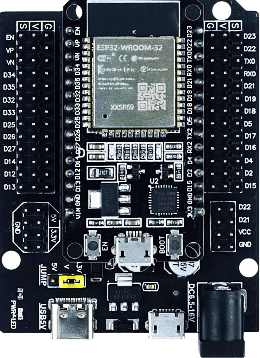
The ESP-32 DEVKIT-V1 with Expansion Board, manufactured by Espressif, is a versatile development board designed for IoT (Internet of Things) applications. It features the powerful ESP32 chip, which integrates Wi-Fi and Bluetooth capabilities, making it ideal for wireless communication projects. The expansion board enhances the functionality of the ESP32 by providing additional GPIO pins, sensor interfaces, and prototyping-friendly features.

Explore Projects Built with ESP-32 DEVKIT-V1 with Expansion Board

Use Cirkit Designer to design, explore, and prototype these projects online. Some projects support real-time simulation. Click "Open Project" to start designing instantly!
ESP32-Based Environmental Monitoring and Alert System with Solar Charging
Image of mark: A project utilizing ESP-32 DEVKIT-V1 with Expansion Board in a practical application
This circuit features an ESP32 Devkit V1 microcontroller connected to various sensors and modules for monitoring and communication purposes. It includes an MQ-2 gas sensor and a DHT11 temperature and humidity sensor, both interfaced with the ESP32 for environmental data collection. The circuit is powered by a 12V battery, regulated to 5V by step-down converters, and includes a solar charge controller connected to a solar panel for battery charging, a UPS module for power management, and a SIM900A module for GSM communication. Additionally, there is a WS2812 RGB LED strip for visual feedback and a piezo buzzer for audio alerts, both controlled by the ESP32.
Cirkit Designer LogoOpen Project in Cirkit Designer
ESP32 and Logic Level Converter-Based Wi-Fi Controlled Interface
Image of Toshiba AC ESP32 devkit v1: A project utilizing ESP-32 DEVKIT-V1 with Expansion Board in a practical application
This circuit features an ESP32 Devkit V1 microcontroller connected to a Bi-Directional Logic Level Converter, which facilitates voltage level shifting between the ESP32 and external components. The ESP32 is powered through its VIN pin via an alligator clip cable, and the logic level converter is connected to various pins on the ESP32 to manage different voltage levels for communication.
Cirkit Designer LogoOpen Project in Cirkit Designer
ESP32-Based Smart Agriculture System with LoRa Communication
Image of Soil Monitoring Device: A project utilizing ESP-32 DEVKIT-V1 with Expansion Board in a practical application
This circuit features an ESP32 Devkit V1 microcontroller as the central processing unit, interfacing with various sensors including a PH Meter, an NPK Soil Sensor, and a Soil Moisture Sensor for environmental data collection. It also includes an EBYTE LoRa E220 module for wireless communication. Power management is handled by a Step Up Boost Power Converter, which is connected to a 12V Battery, stepping up the voltage to power the ESP32 and sensors, with common ground connections throughout the circuit.
Cirkit Designer LogoOpen Project in Cirkit Designer
ESP32-Based Environmental Monitoring and Alert System with Solar Charging
Image of Schematic: A project utilizing ESP-32 DEVKIT-V1 with Expansion Board in a practical application
This circuit features an ESP32 Devkit V1 microcontroller connected to various sensors and devices, including a DHT11 temperature and humidity sensor, an MQ-2 gas sensor, and a WS2812 RGB LED strip. The ESP32 controls the LED strip and processes sensor readings, while a SIM900A module provides cellular communication capabilities. Power management is handled by a UPS module fed by a 12V battery charged via a solar panel and charge controller, with voltage regulation provided by step-down converters. Additionally, a piezo buzzer is included for audible alerts, and the system's safety is ensured by a circuit breaker connected to a switching power supply for AC to DC conversion.
Cirkit Designer LogoOpen Project in Cirkit Designer

Explore Projects Built with ESP-32 DEVKIT-V1 with Expansion Board

Use Cirkit Designer to design, explore, and prototype these projects online. Some projects support real-time simulation. Click "Open Project" to start designing instantly!
Image of mark: A project utilizing ESP-32 DEVKIT-V1 with Expansion Board in a practical application
ESP32-Based Environmental Monitoring and Alert System with Solar Charging
This circuit features an ESP32 Devkit V1 microcontroller connected to various sensors and modules for monitoring and communication purposes. It includes an MQ-2 gas sensor and a DHT11 temperature and humidity sensor, both interfaced with the ESP32 for environmental data collection. The circuit is powered by a 12V battery, regulated to 5V by step-down converters, and includes a solar charge controller connected to a solar panel for battery charging, a UPS module for power management, and a SIM900A module for GSM communication. Additionally, there is a WS2812 RGB LED strip for visual feedback and a piezo buzzer for audio alerts, both controlled by the ESP32.
Cirkit Designer LogoOpen Project in Cirkit Designer
Image of Toshiba AC ESP32 devkit v1: A project utilizing ESP-32 DEVKIT-V1 with Expansion Board in a practical application
ESP32 and Logic Level Converter-Based Wi-Fi Controlled Interface
This circuit features an ESP32 Devkit V1 microcontroller connected to a Bi-Directional Logic Level Converter, which facilitates voltage level shifting between the ESP32 and external components. The ESP32 is powered through its VIN pin via an alligator clip cable, and the logic level converter is connected to various pins on the ESP32 to manage different voltage levels for communication.
Cirkit Designer LogoOpen Project in Cirkit Designer
Image of Soil Monitoring Device: A project utilizing ESP-32 DEVKIT-V1 with Expansion Board in a practical application
ESP32-Based Smart Agriculture System with LoRa Communication
This circuit features an ESP32 Devkit V1 microcontroller as the central processing unit, interfacing with various sensors including a PH Meter, an NPK Soil Sensor, and a Soil Moisture Sensor for environmental data collection. It also includes an EBYTE LoRa E220 module for wireless communication. Power management is handled by a Step Up Boost Power Converter, which is connected to a 12V Battery, stepping up the voltage to power the ESP32 and sensors, with common ground connections throughout the circuit.
Cirkit Designer LogoOpen Project in Cirkit Designer
Image of Schematic: A project utilizing ESP-32 DEVKIT-V1 with Expansion Board in a practical application
ESP32-Based Environmental Monitoring and Alert System with Solar Charging
This circuit features an ESP32 Devkit V1 microcontroller connected to various sensors and devices, including a DHT11 temperature and humidity sensor, an MQ-2 gas sensor, and a WS2812 RGB LED strip. The ESP32 controls the LED strip and processes sensor readings, while a SIM900A module provides cellular communication capabilities. Power management is handled by a UPS module fed by a 12V battery charged via a solar panel and charge controller, with voltage regulation provided by step-down converters. Additionally, a piezo buzzer is included for audible alerts, and the system's safety is ensured by a circuit breaker connected to a switching power supply for AC to DC conversion.
Cirkit Designer LogoOpen Project in Cirkit Designer

Common Applications and Use Cases

  • IoT devices and smart home automation
  • Wireless sensor networks
  • Wearable technology
  • Robotics and automation systems
  • Prototyping and educational projects

Technical Specifications

Key Technical Details

Parameter Specification
Microcontroller ESP32 (dual-core Xtensa LX6 processor)
Clock Speed Up to 240 MHz
Flash Memory 4 MB (varies by model)
SRAM 520 KB
Wireless Connectivity Wi-Fi 802.11 b/g/n, Bluetooth 4.2 (Classic + BLE)
Operating Voltage 3.3V
Input Voltage (VIN) 5V (via USB or external power supply)
GPIO Pins 30+ (varies with expansion board)
ADC Channels 18 (12-bit resolution)
DAC Channels 2 (8-bit resolution)
Communication Interfaces UART, SPI, I2C, I2S, PWM
Power Consumption Ultra-low power modes available
Dimensions 54 mm x 27 mm (approx.)

Pin Configuration and Descriptions

The ESP-32 DEVKIT-V1 with Expansion Board provides a variety of pins for interfacing with peripherals. Below is the pinout description:

Pin Name Functionality Description
VIN Power Input Accepts 5V input from USB or external source
GND Ground Common ground for the circuit
3V3 Power Output Provides 3.3V output for peripherals
EN Enable Resets the chip when pulled low
GPIO0 General Purpose I/O Used for boot mode selection
GPIO2 General Purpose I/O Can be used as PWM, ADC, or other functions
GPIO4 General Purpose I/O Supports ADC, PWM, and other functions
GPIO21 SDA (I2C) I2C data line
GPIO22 SCL (I2C) I2C clock line
TXD0 UART Transmit UART0 TX for serial communication
RXD0 UART Receive UART0 RX for serial communication
ADC1_CH0 Analog Input ADC channel 0 for analog signal measurement
DAC1 Digital-to-Analog Converter DAC output channel 1

Note: The exact pin availability and functionality may vary depending on the specific expansion board used.

Usage Instructions

How to Use the Component in a Circuit

  1. Powering the Board:

    • Connect the ESP-32 DEVKIT-V1 to your computer using a micro-USB cable. This will power the board and allow programming.
    • Alternatively, supply 5V to the VIN pin and connect GND to the ground of your power source.
  2. Programming the Board:

    • Install the Arduino IDE and add the ESP32 board support package via the Board Manager.
    • Select "ESP32 Dev Module" from the Tools > Board menu.
    • Connect the board to your computer and select the appropriate COM port.
  3. Connecting Peripherals:

    • Use the GPIO pins to connect sensors, actuators, or other peripherals.
    • Ensure that the voltage levels of connected devices are compatible with the 3.3V logic of the ESP32.
  4. Uploading Code:

    • Write your code in the Arduino IDE or another supported environment.
    • Click the upload button to flash the code to the ESP32.

Important Considerations and Best Practices

  • Voltage Levels: The ESP32 operates at 3.3V logic. Avoid connecting 5V signals directly to GPIO pins to prevent damage.
  • Boot Mode: Ensure GPIO0 is pulled low during boot to enter programming mode.
  • Power Supply: Use a stable power source to avoid unexpected resets or instability.
  • Wi-Fi Antenna: Avoid placing metal objects near the onboard antenna to ensure optimal wireless performance.

Example Code for Arduino UNO Integration

Below is an example of using the ESP-32 DEVKIT-V1 to read data from a DHT11 temperature and humidity sensor and send it to a serial monitor:

#include <WiFi.h>
#include <DHT.h>

// Define DHT sensor type and pin
#define DHTPIN 4       // GPIO4 is connected to the DHT sensor
#define DHTTYPE DHT11  // DHT11 sensor type

DHT dht(DHTPIN, DHTTYPE);

void setup() {
  Serial.begin(115200);  // Initialize serial communication
  dht.begin();           // Initialize the DHT sensor
  Serial.println("DHT11 Sensor Test");
}

void loop() {
  delay(2000);  // Wait 2 seconds between readings

  // Read temperature and humidity
  float humidity = dht.readHumidity();
  float temperature = dht.readTemperature();

  // Check if readings are valid
  if (isnan(humidity) || isnan(temperature)) {
    Serial.println("Failed to read from DHT sensor!");
    return;
  }

  // Print readings to the serial monitor
  Serial.print("Humidity: ");
  Serial.print(humidity);
  Serial.print("%  Temperature: ");
  Serial.print(temperature);
  Serial.println("°C");
}

Note: Ensure the DHT sensor is connected to GPIO4 and powered with 3.3V or 5V.

Troubleshooting and FAQs

Common Issues Users Might Face

  1. Board Not Detected by Computer:

    • Ensure the USB cable is functional and supports data transfer.
    • Install the correct USB-to-serial driver for the ESP32.
  2. Code Upload Fails:

    • Check that the correct COM port and board type are selected in the Arduino IDE.
    • Hold the "BOOT" button on the ESP32 while uploading the code.
  3. Wi-Fi Connection Issues:

    • Verify the SSID and password in your code.
    • Ensure the Wi-Fi network is within range and operational.
  4. Unstable Operation:

    • Use a stable power supply with sufficient current (at least 500mA).
    • Avoid excessive load on GPIO pins.

Solutions and Tips for Troubleshooting

  • Reset the Board: Press the "EN" button to reset the ESP32 if it becomes unresponsive.
  • Check Connections: Verify all wiring and connections to ensure proper functionality.
  • Debugging: Use the Serial Monitor in the Arduino IDE to print debug messages and identify issues.

By following this documentation, users can effectively utilize the ESP-32 DEVKIT-V1 with Expansion Board for a wide range of IoT and prototyping applications.